
User guide

Teledyne Analytical Instruments
1-6 Part
1 Introduction Model 2010A
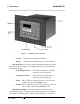
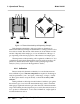
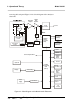
Figure 1-2: Model 2010A Rear Panel
• Power Connection 85-250VACpowersource.
• Analog Outputs 0-1Vdcconcentrationplus0-1Vdc
rangeID,andisolated4-20mAdcplus
4-20mAdcrangeID.
• Alarm Connections 2concentrationalarmsand1system
alarm.
• RS-232 Port Serial digital concentration signal out-
put and control input.
• Remote Probe Usedinthe2010Atointerfacetheex-
ternal Analysis Unit.
• Remote Span/Zero Digitalinputsallowexternalcontrolof
analyzercalibration.
• Calibration Contact To notify external equipment that in-
strumentisbeingcalibratedandread-
ings are not monitoring sample.
• Range ID Contacts Fourseparate,dedicated,range-identi-
cationrelaycontacts(01,02,03,CAL).
• Network I/O Serial digital communications for local
networkaccess.Forfutureexpansion.
Not implemented at this printing.
Note: If you require highly accurate Auto-Cal timing, use external