
User guide

Part I 1-3
Teledyne Analytical Instruments
Thermal Conductivity Analyzer Part I: Control Unit
• Microprocessorbasedelectronics:8-bitCMOSmicroprocessor
with32kBRAMand128kBROM.
• Autoandremotecalibrationcapabilities.
• Fouranalogoutputs:twoformeasurement(0–1VdcandIso-
lated4–20mAdc)andtwoforrangeidentication.
• Compactandversatiledesign:Smallfootprint,yetinternalcom-
ponentsareaccessible.
1.4 Model Designations
The Model 2010A is ordinarily custom programmed at the factory to
t the customer’s application. Many parameters, including the number of
channels, the gas application, the materials specication of the sampling
system, and others, are options. The most common options, are covered in
this manual. See the Specic Model Information checklist in the front mat-
ter of this manual for those that apply to your Model 2010A analyzer. Some
standard models that are not covered in this manual are listed here.
Models 2000A: Bothanalysissectionandcontrolunitareinasingle
general purpose enclosure.
Models 2020: Boththeanalysissectionandcontrolunitareinasingle
explosion proof enclosure.
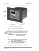
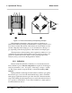
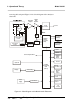
1.5 Operator Interface (Front Panel)
The standard 2010A is housed in a rugged metal case with all controls
and displays accessible from the front panel. See Figure 1-1. The front
panel has thirteen buttons for operating the analyzer, a digital meter, and an
alphanumeric display. They are described briey here and in detail in the
Operations chapter of this manual.
Function Keys: Six touch-sensitive membrane switches are used to
change the specic function performed by the analyzer:
• Analyze Perform analysis for target-gas content of a sample
gas.
• System Performsystem-relatedtasks(describedindetailin
chapter 4, Operation.).
• Span Spancalibratetheanalyzer.
• Zero Zerocalibratetheanalyzer.