
User Manual


Maintenance 2000 XTC
Maintenance
4.1 Routine Maintenance
Aside from normal cleaning and checking for leaks at the gas
connections, routine maintenance is limited to recalibration. For
calibration procedures, refer to Section 3.6. On occasion, it may be
necessary to replace a blown fuse. This is covered in section 4.2.
WARNING: SEE WARNINGS ON THE TITLE PAGE OF THIS
MANUAL.
The overall design of th e instrument is intended to facilitate servicing
and troubleshooting, should that ever be necessary. The sensor itself is a
solid-state unit with no serviceable p arts. Th e cell is enclosed in an
insulated co mpartm ent that is r eadily accessible af ter rem oving the
transmitter cover. Th ere are three (3) PC boards handling the electronics:
one in the transmitter module and tw o in the galvanic isolator module. Both
boards are easily accessib le after rem oving the respective front covers.
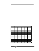
4.2 Troubleshooting
The following table offers guidelines for diagnosing and correcting
common problems associated with the 2000 XTC Thermal Conductivity
Transmitter.
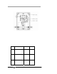
Table 4-1 Troubleshooting
Symptom Cause Remedy
The unit will not
power up.
Power not connected
or a wire has pulled
loose.
A) Make sure 24VDC po wer
is connected and turned
on.
B) Check input power wi ring
at rear of gal van ic isola tor
module.
Teledyne Analytical Instruments 22