
User Manual


Thermal Conductivity Transmitter Installation
CAUTION: THIS INSTRUMENT IS DESIGNED TO HA NDLE
HAZARDOUS GASES. WHENEVER A FITTING IS
OPENED, USE A NEW FERRULE AND CONE TO
SECURE A GAS TIGHT SEAL. EACH FITTING MUST
BE LEAK CHECKED WHENEVER A CONNECTION
HAS BEEN OPENED OR DISTURBED IN ANY
MANNER.
The inlet gas pressure should be regulated between 2-20 psig. A
flow control device should be installed before the “sample in” port in
order to keep the gas flow between 0.4 and 2 SCFH.
If greater flow is required for improved response time (over 20
SCFH), install a bypass in the samp li ng system upstream of the analyzer
input.
Exhaust connections must be consistent with the hazard level of
the constituent gases. Check local, state, and federal laws, to ensure
the exhaust stream vents to an appropriately controlled area if
required. The exhaust should be vented to atmospheric pressure or
returned to the process line. Use care not to create backpressure in
the vent line.
3.5 Electrical Connections
The Thermal Conductivity Transmitter requires three electrical
connections:
24 VDC power input •
•
•
Signal output (4-20 mA current output)
Interconnection cable
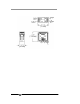
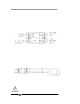
Power and output signal connections are made to the galvanic
isolator module according to the interconnection diagram C-74837
included at the back of this manual. See also Figure 3-3.
24VDC Power Connection
The 24VDC power supply can deliver a maximum of 10.8 watts to
power the heaters and drive the electronics in both the galvanic isolator
and the transmitter modules. Connect the positive lead from the 24 VDC
source to terminal 7 and the negative lead to term inal 8 on the galvanic
isolator module as shown in Figure 3-3.
Teledyne Analytical Instruments 15