
User Manual


Thermal Conductivity Transmitter Operational Theory
2.4 Electronics and Signal Processing
For safety reasons, the electronics and signal processing section are
located remotely from the transmitter module. A galvanic isolator is
employed to limit the current that ca n be passed through the interconnect
cable to levels that are incapable of providing an ignition source. The
galvanic isolator also provides an optically-isolated 4-20 mA output
signal reconstructed from the 0-4 mA output signal sent from the
transmitter. All electronics in the transmitter are contained on a single
PC board accessible by removing the front cover. The transmitter is
powered from two (2) separate 15VDC lines from the galvanic isolator
module. The galvanic isolator incorporates a 24VDC power supply.
The processing electronics for the sensor are located inside the
transmitter case in addition to the sample cell heaters and E-to-I
converter. The control circuitry for the sample cell heaters, the 24 VDC
power supply, and electronics used to condition the output signal are
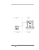
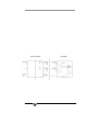
located in the galvanic isolator case. Figure 2-4 is a block diagram of the
instrument electronics.
Figure 2-4: Block Diagram of 2000 XTC
2.4.1 Transmitter
The differences in thermal conductivities of the sample gas provide
a small but detectable change in temperature of the resistive sensor
Teledyne Analytical Instruments 9