
User Manual


Operational Theory 2000 XTC
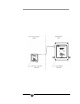
Figure 2-2: Recommended External Sample System
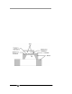
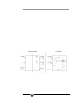
The sample path within the transm itter is a straight-through path.
Gas encounters no dead space. This minimizes residual gas pockets that
can interfere with accurate analysis.
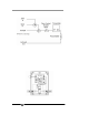
Stainless steel 1/4” tube fittings are installed (6mm are available)
for connecting the external sample system to the transmitter. For metric
system installations, 6 mm adapters can be supplied if needed. The
sample gas path through the transmitter is shown in Figure 2-3.
Figure 2-3: Internal Piping
Teledyne Analytical Instruments 8