OPERATING INSTRUCTIONS FOR 2000 XTC Thermal Conductivity Transmitter P/N M74838 ECO: 04-0203 REV 1 DANGER Toxic gases and/or flammable liquids may be present in this monitoring system. Personal protective equipment may be required when servicing this instrument. Hazardous voltages exist on certain components internally which may persist for a time even after the power is turned off and disconnected. Only authorized personnel should conduct maintenance and/or servicing.
000 XTC Before conducting any maintenance or servicing, consult with authorized supervisor/manager. Copyright © 2002 Teledyne Analytical Instruments All Rights Reserved.
Thermal Conductivity Transmitter Specific Model Information It is not recommended that this instrument be used for analysis on any other gas or gas mixture than that specified at the time of purchase. Thermal conductivity analyzers are calibrated at the factory for a specific application using a known gas mixture that is representative of the customers’ process. Using this instrument to analyze any other gas mixture may result in serious error.
2000 XTC Safety Messages Your safety and the safety of others is very important. We have provided many important safety messages in this manual. Please read these messages carefully. A safety message alerts you to potential hazards that could hurt you or others. Each safety message is associated with a safety alert symbol. These symbols are found in the manual and inside the instrument.
Thermal Conductivity Transmitter IF YOU USE THE ANALYZER IN A MANNER OTHER THAN THAT FOR WHICH IT WAS INTENDED, UNPREDICTABLE BEHAVIOR COULD RESULT POSSIBLY ACCOMPANIED WITH HAZARDOUS CONSEQUENCES. This manual provides information designed to guide you through the installation, calibration operation and maintenance of your new analyzer. Please read this manual and keep it available.
2000 XTC Table of Contents List of Figures viii List of Tables ix Introduction………………………………………………………………1 1.1 Overview 1 1.2 Typical Applications 1 1.3 Main Features of the Transmitter 2 1.4 Operator Interface 2 Operational Theory……………………………………………………...5 2.1 Introduction 5 2.2 The Thermal Conductivity Sensor 5 2.3 Sample System 7 2.4 Electronics and Signal Processing 9 2.4.1 Transmitter 9 2.4.2 Galvanic Isolator 10 2.5 Connection Cable 11 Installation………………………………………………………………12 3.
Thermal Conductivity Transmitter Maintenance…………………………………………………………….22 4.1 Routine Maintenance 22 4.2 Troubleshooting 22 4.3 Fuse Replacement 24 Appendix………………………………………………………………...26 Specifications 26 Recommended Spare Parts List 28 Reference Drawings 28 Index……………………………………………………………………...
2000 XTC List of Figures Figure 1-1: XTC Transmitter Modules…………………………………..3 Figure 2-1: Thermal Conductivity Sensor ………………………………6 Figure 2-2: Recommended External Sample System…………………8 Figure 2-3: Internal Piping………………………………………………..8 Figure 2-4: Block Diagram of 2000 XTC………………………………..9 Figure 2-5: Model 2000 XTC External Wiring Diagram……………..11 Figure 3-1: Mounting Dimensions for Sensor Unit…………………...
Thermal Conductivity Transmitter List of Tables Table 3-1: Heater Temperature…………………………………..19 Table 3-2: Concentration from Output Current………………….21 Table 4-1 Troubleshooting………………………………………...
2000 XTC DANGER COMBUSTIBLE GAS USAGE WARNING This instrument is approved as an intrinsically safe gas analyzer for usage in a category (ib) Group IIC hazardous area. This approval applies only to the equipment specified and installed in accordance with the information contained within this manual. It is the customer's responsibility to ensure safety, especially when combustible gases are being analyzed since the potential of gas leaks always exists.
Thermal Conductivity Transmitter Introduction Introduction 1.1 Overview The Teledyne Analytical Instruments 2000 XTC Thermal Conductivity Transmitter is an instrument designed to analyze the gas concentration of a binary gas mixture. This manual covers the CENELEC/ATEX approved model 2000 XTC Thermal Conductivity Transmitter. These units are rated as intrinsically safe and may be used in Class I, Group A, B, C, D, Div. 1 (North America) and EEx ib IIC T3 (IEC/Europe) hazardous environments. 1.
Introduction • 2000 XTC He in N2 (or air) 0-5%, 0-8% 0-10%, 0-30%, 0-100% • Natural Gas in Methane 0-20%, 0-50%, 0-100% • Nitrogen (or air) in CO2 0-10%, 0-20%, 0-50%, 0-100% 1.3 Main Features of the Transmitter The 2000 XTC Thermal Conductivity Transmitter is sophisticated yet simple to use. It provides a 4-20 mA output signal proportional to the concentration of one component of a gas mixture.
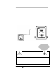
Thermal Conductivity Transmitter Introduction Figure 1-1 shows the 2000 XTC Thermal Conductivity Transmitter. The instrument is comprised of two modules: the transmitter unit and the galvanic isolator unit. The transmitter is located at the sample point (which can be a hazardous area) and is where the sample gas input is converted into an electrical output signal. The galvanic isolator module contains the 24V power supply, the power isolation safety barrier and signal output connection.
Operational Theory Teledyne Analytical Instruments 2000 XTC 4
Thermal Conductivity Transmitter Operational Theory Operational Theory 2.1 Introduction The 2000 XTC is comprised of two subsystems: 1. The thermal conductivity sensor and transmitter 2. Galvanic isolator and power supply The system directs a sample gas into the transmitter. Internally, the sample is passed to the sensor and heated without contaminating or altering the sample in any way.
Operational Theory 2000 XTC instrument for analyzing other gas mixtures. Generally, the user must be able to calibrate the instrument with a gas containing the host gas and a known concentration of the impurity or gas to be analyzed. At a minimum, a zero gas and a mixture containing approximately 70-100% of the species to be analyzed on the range of interest should be provided in order to properly calibrate this instrument. Figure 2-1 shows a cross section of the sensor used in the 2000 XTC.
Thermal Conductivity Transmitter Operational Theory Control circuitry precisely regulates the temperature of the measuring cell. These additional controlled heaters are installed to heat the sample gas and compensate for ambient temperature fluctuations, enhancing the stability and accuracy of the measuring process. The heater temperature is adjustable using a set-screw adjustment potentiometer inside the transmitter unit. Control of the sample and supporting gases is not provided in the basic design.
Operational Theory 2000 XTC Figure 2-2: Recommended External Sample System The sample path within the transmitter is a straight-through path. Gas encounters no dead space. This minimizes residual gas pockets that can interfere with accurate analysis. Stainless steel 1/4” tube fittings are installed (6mm are available) for connecting the external sample system to the transmitter. For metric system installations, 6 mm adapters can be supplied if needed.
Thermal Conductivity Transmitter Operational Theory 2.4 Electronics and Signal Processing For safety reasons, the electronics and signal processing section are located remotely from the transmitter module. A galvanic isolator is employed to limit the current that can be passed through the interconnect cable to levels that are incapable of providing an ignition source.
Operational Theory 2000 XTC membrane. The amount of voltage needed to offset the analog output (i.e. to null the circuit when the resistance changes due to temperature effects) is measured and applied. A preprogrammed microcontroller with EPROM uses the offset voltage from the analog stages to generate a linearized output voltage signal, which is then converted to a 0-4 mA current.
Thermal Conductivity Transmitter Operational Theory The 24 VDC input is fed to the primary side of an input transformer. The input circuit is fused via a 400 mA fuse and incorporates a diode protection circuit in case of accidental reverse polarity connection. The signal output is also fused, with a 50 mA fuse protecting the 420 mA output terminal. This terminal is also isolated using a high linearity optocoupler with its own power-limiting circuitry.
Installation 2000 XTC Installation For Intrinsically Safe (IS) installation, special considerations are required. The 2000 XTC Thermal Conductivity Transmitter has been designed to be Intrinsically Safe using an integral galvanic isolator module that limits power to and from the transmitter in a hazardous location. When properly installed, this design utilizes redundant safety features to prevent the transmitter from becoming an ignition source in the event of a circuit failure.
Thermal Conductivity Transmitter Installation 3.2 Mounting the Transmitter The Model 2000 XTC Transmitter is intended for indoor use only. The transmitter module is designed for operation in a hazardous location. It should be mounted in an area close to the sample takeoff point. Refer to Figure 3-1 for mounting information and dimensions. The calibration and temperature control adjustment potentiometers are located under the top cover of the transmitter.
Installation 2000 XTC Figure 3-2: Mounting Dimensions for Interface Unit Once the transmitter and galvanic isolator are securely mounted, connect the interface cable to the transmitter. If the cable is not attached to the safety barrier, connect the wires to the unit as described in Section 3-5. The transmitter end of the cable is fitted with a 5-pin connector. Secure the cable to the mating connector on the transmitter. 3.
Thermal Conductivity Transmitter CAUTION: Installation THIS INSTRUMENT IS DESIGNED TO HANDLE HAZARDOUS GASES. WHENEVER A FITTING IS OPENED, USE A NEW FERRULE AND CONE TO SECURE A GAS TIGHT SEAL. EACH FITTING MUST BE LEAK CHECKED WHENEVER A CONNECTION HAS BEEN OPENED OR DISTURBED IN ANY MANNER. The inlet gas pressure should be regulated between 2-20 psig. A flow control device should be installed before the “sample in” port in order to keep the gas flow between 0.4 and 2 SCFH.
Installation 2000 XTC 4-20 mA Output Signal The output signal from the instrument is available to the user as a 4-20 mA current. It has a maximum impedance of 700 Ohms. Typically, this output is used to display concentration using a digital meter or chart recorder or to trigger an alarm circuit. Referring again to Figure 3-3, connect the positive lead to terminal 12 and the negative lead to terminal 11 on the galvanic isolator module.
Thermal Conductivity Transmitter Installation INSTRUMENT USE ONLY AN APPROVED INTERCONNECTION CABLE. SEE THE SPARE PARTS LIST IN THE APPENDIX OF THIS MANUAL FOR AN APPROVED FACTORY REPLACEMENT CABLE. For intrinsically safe installation, use only the cable supplied by the factory. Run length should not exceed 30.5 meters (100 ft). 3.6 Calibration Note: Calibration frequency of the 2000XTC is highly dependent on gas application.
Installation 2000 XTC Figure 3-5: Temperature and Calibration Adjustment Location 3.6.1 Adjusting Cell Block Temperature Note: A separate heater inside the transmitter case controls the transmitter cell block temperature. It has been adjusted at the factory for optimum performance based on your application. Depending on the location of the transmitter and your process application, it may be necessary to adjust the temperature of the internal heaters.
Thermal Conductivity Transmitter Installation stabilization of the heater before continuing with the calibration. 3. If the output is still fluctuating after 15 minutes, continue making small adjustments to the temperature until the output signal stabilizes. Table 3-1: Concentration from Output Current Heater Temperature (°C) Voltage at U1 pin 12 (V) 20° 2.04 V 25° 2.25 V 30° 2.45 V 35° 2.62 V 40° 2.78 V 45° 2.92 V 50° 3.04 V 55° 3.15 V 60° 3.24 V 65° 3.32 V 3.6.
Installation 2000 XTC zeroing this instrument when using a gas different than the gas specified at the time of purchase. To zero calibrate this instrument: 1. Connect a read-out device to the 4-20 mA output signal terminals on the galvanic isolator module according to Section 3-5. 2. If the transmitter cover has not been removed, unscrew the 4 cover screws and remove the top cover. 3. Allow zero gas to pass into the transmitter.
Thermal Conductivity Transmitter Installation To span calibrate this instrument: 1. Connect a read-out device to the 4-20 mA output signal terminals on the galvanic isolator module according to Section 3-5. 2. If the transmitter cover has not been removed, unscrew the 4 cover screws and remove the top cover. 3. Allow span gas to flow through the transmitter. After a few moments, the output device should respond to the known concentration of gas in the span gas mixture. 4.
Maintenance 2000 XTC Maintenance 4.1 Routine Maintenance Aside from normal cleaning and checking for leaks at the gas connections, routine maintenance is limited to recalibration. For calibration procedures, refer to Section 3.6. On occasion, it may be necessary to replace a blown fuse. This is covered in section 4.2. WARNING: SEE WARNINGS ON THE TITLE PAGE OF THIS MANUAL. The overall design of the instrument is intended to facilitate servicing and troubleshooting, should that ever be necessary.
Thermal Conductivity Transmitter Symptom Cause Blown fuse on input power circuit. No output signal Blown fuse Maintenance Remedy Check fuse and replace if necessary with 400 mA fuse. See Section 4.3. A) Check fuse on signal output circuit. Replace if necessary with 50 mA fuse. See Section 4.3. B) Check fuse on output power circuit. Replace if necessary with 200mA fuse. See Section 4.3. Erratic output signal Cable disconnected or broken Check power cable in transmitter module. See Figure 4.1.
Maintenance 2000 XTC Figure 4-1: Cable Identification in Transmitter 4.3 Fuse Replacement There are four fuses installed in the galvanic isolator module for circuit protection. The main fuse (F1) is accessible after removing the fuse holder cover. All other fuses require separating the 2 galvanic isolator modules. See Figure 4-2 for fuse identification. Table 4-1 lists the fuse rating, TAI part number, and the applicable circuit it serves to protect.
Thermal Conductivity Transmitter Maintenance To replace the main power fuse (F1): • Disconnect power to the instrument • Use a flat blade screwdriver to remove the fuse holder cover. Push in with the screwdriver and turn counterclockwise. • Pull out the blown fuse and replace with an exact replacement according to Table 4-2. • Replace cover and power up instrument. Figure 4-2 Fuse Location To remove the other fuses: • Disconnect power to the instrument.
Appendix 2000 XTC Appendix Specifications System: Dual module: transmitter and galvanic isolator Enclosure: Galvanic isolator: plastic DIN mountable case Transmitter: aluminum case, panel mountable, Nema 4X, IEC 60529 and IP 66 rated Classification: ATEX EEx ib IIC T3 (Europe) Power Requirements: 24VDC, 10.8 watt max power consumption (8 watts normal) Ranges: Specific application determined by user. See Section 1.2 for example ranges.
Thermal Conductivity Transmitter Appendix Flow Rate 0.4-2.0 SCFH Internal Heater: 2—1.5W heaters Temp Control: Factory set to 20 ± 2°C User settable Calibration Controls: Zero, span and temperature control Fuses: Input power circuit: 400 mA Output Signal Circuit: 50 mA Heater Circuit: (2) 160 mA Mounting (transmitter): Wall-mount (see section 3.2) Mounting (interface unit): DIN-rail mounting (see section 3.
Appendix 2000 XTC Recommended Spare Parts List Qty.
Thermal Conductivity Transmitter Index Index accuracy 10, 26 address 28 adjustment location 18 analog signal 6 analog stages 10 analysis range 1, 6 applications 1 ATEX 1 background gas 5 binary gas mixture 5 block diagram 9 bypass line 15 cable See interface cable cable identification 24 cable run length 17 calibration 5, 6, 17 internal temperature 18 span 20 zero 19 calibration controls 27 calibration point 5 calibration points 2 caution sign iv cell block 2, 7, 26 chart recorder 2 classification 26 comb
Index 2000 XTC output signal 2, 5, 6, 10 0-4 mA 9, 11, 16 4-20 mA 9, 16 PC board 9, 17, 22 pin configuration 11 potentiometer 7, 13, 17 power fluctuation 10 power limiting 10 power output 10 power requirements 26 power supply 3, 5, 9, 15 pressure 26 pressure regulation 7, 15 purge 19 reference See calibration point reference drawings See drawings regulator 7 resistance 5 resistor pair 6 response time 15, 26 routine maintenance 22 safety barrier 3 safety information iv sample path 8 sample system 7 sensor