
Instruction Manual

Thermal Conductivity Analyzer Operation 4
4-13
Teledyne Analytical Instruments
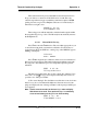
Then, and whenever Slope is less than 0.01 for at least 3 min, instead of
Slope you will see a countdown: 9 Left, 8 Left, and so fourth. These are
software steps in the zeroing process that the system must complete, AFTER
settling, before it can go back to
Analyze
. Software zero is indicated by S
Zero in the lower right corner.
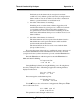
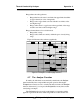
###### % O2 N2
4 Left=##### SZero
The zeroing process will automatically conclude when the output is within
the acceptable range for a good zero. Then the analyzer automatically returns to
the
Analyze
mode.
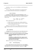
4.4.1.2 Manual Mode Zeroing
Press
Zero
to enter the
Zero
function. The screen that appears allows you
to select between automatic or manual zero calibration. Use the ∆∇ keys to
toggle between AUTO and MAN zero settling. Stop when MANUAL appears,
blinking, on the display.
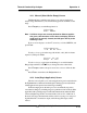
Select zero
mode: MANUAL
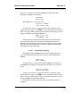
Press
Enter
to begin the zero calibration. After a few seconds the first of
three zeroing screens appears. The number in the upper left hand corner is the
first-stage zero offset. The microprocessor samples the output at a predeter-
mined rate.
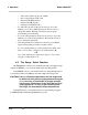
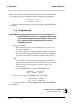
#### % O 2 N 2
Zero adj:2048 CZero
The analyzer goes through C–Zero, F–Zero, and S–Zero. During C–Zero
and F–Zero, use the
∆∆
∆∆
∆∇ keys to adjust displayed Zero adj: value as close as
possible to zero. Then, press
Enter
.
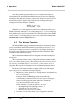
S–Zero starts. During S–Zero, the Microcontroller takes control as in Auto
Mode Zeroing, above. It calculates the differences between successive sam-
plings and displays the rate of change as Slope= a value in parts per million per
second (ppm/s).
Note: It takes several seconds for the true Slope value to display.
Wait about 10 seconds. Then, wait until Slope is sufficiently
close to zero before pressing
Enter
to finish zeroing.
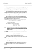
#### % O 2 N 2
Slope=##### CZero