
Instruction Manual

4 Operation Model 2000A-EU
4-10
Teledyne Analytical Instruments
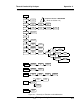
Power: OK Analog: OK
Cell: 2 Preamp: 3
The module is functioning properly if it is followed by OK. A number
indicates a problem in a specific area of the instrument. Refer to Chapter 5
Maintenance and Troubleshooting for number-code information. The results
screen alternates for a time with:
Press Any Key
To Continue...
Then the analyzer returns to the initial System screen.
4.3.6 The Model Screen
Move the < > arrow key to MORE and press
Enter
. With MODEL
blinking, press
Enter
. The screen displays the manufacturer, model, and soft-
ware version information.
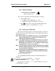
4.3.7 Checking Linearity with ALGORITHM
From the
System
Function screen, select ALGORITHM, and press
Enter
.
Range linearization
> Ø 1 Ø 2 Ø 3 <
Use the < > keys to select the range: 01, 02, or 03. Then press
Enter
.
Range: Ø 16 %
Gas use: O2 N2
Press Enter again.
Algorithm setup:
VERIFY SET UP
Select and
Enter
VERIFY to check whether the linearization has been
accomplished satisfactorily.
Dpt INPUT OUTPUT
Ø Ø.ØØ Ø.ØØ
The leftmost digit (under Dpt) is the number of the data point being moni-
tored. Use the ∆∇ keys to select the successive points.
The INPUT value is the input to the linearizer. It is the simulated output of
the analyzer. You do not need to actually flow gas.