
Instruction Manual

Teledyne Analytical Instruments
3 Installation Model 2000A-EU
3-6
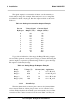
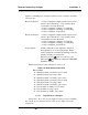
The signal output for concentration is linear over the currently se-
lected analysis range. For example, if the analyzer is set on a range that
was defined as 0–10 % hydrogen, then the output would be as shown in
Table 3-2.
Table 3-2: Analog Concentration Output—Example
Percent Voltage Signal Current Signal
Hydrogen Output (V dc) Output (mA dc)
0 0.0 4.0
1 0.1 5.6
2 0.2 7.2
3 0.3 8.8
4 0.4 10.4
5 0.5 12.0
6 0.6 13.6
7 0.7 15.2
8 0.8 16.8
9 0.9 18.4
10 1.0 20.0
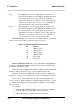
To provide an indication of the range, the Range ID analog outputs
are used. They generate a steady preset voltage (or current when using the
current outputs) to represent a particular range. Table 3-3 gives the range
ID output for each analysis range.
Table 3-3: Analog Range ID Output—Example
Range Voltage (V) Current (mA) Application
Range 1 0.25 8 0-1 % H
2
in N
Range 2 0.50 12 0-10 % H
2
in N
Range 3 0.75 16 0-1 % H
2
in Air
Range 4 (Cal) 1.00 20 0-1 % H
2
in N
3.3.3.2 Alarm Relays
The nine alarm-circuit connector pins connect to the internal alarm
relay contacts. Each set of three pins provides one set of Form C relay
contacts. Each relay has both normally open and normally closed contact
connections. The contact connections are shown in Table 3-4. They are