
Manual

v
Teledyne Analytical Instruments
Table of Contents
Introduction
1.1 Overview........................................................................... 1-1
1.2 Description........................................................................ 1-1
1.2.1 System Chassis ............................................................ 1-2
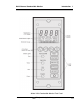
1.2.2 Control Unit ................................................................... 1-2
1.2.3 Channel Modules .......................................................... 1-2
1.2.3.1 Main Featuress of the Channel Module ............... 1-2
1.2.4 Detector......................................................................... 1-2
1.2.5 Terminal Strip Housing .................................................. 1-2
Operational Theory
2.1 Introduction .................................................................... 2-1
2.2 System Chassis ............................................................. 2-1
2.3 Control Unit .................................................................... 2-1
2.4 Channel Module............................................................. 2-3
2.5 Combustible Sensors ..................................................... 2-3
2.5.1 Response of Combustibles to Various Gases .............. 2-7
Installation
3.1 Unpacking the Analyzer ................................................. 3-1
3.2 System Chassis ............................................................. 3-2
3.2.1 Location ................................................................ 3-2
3.2.2 Power .................................................................... 3-2
3.2.3 Electrical Connections .......................................... 3-2
3.3 Control Unit .................................................................... 3-5
3.3.1 ControlUnit Fuses........................................................ 3-5
3.3.2 Control Unit Jumper Settings ...................................... 3-6
3.4 Channel Modules ........................................................... 3-8
3.4.1 Removing the Channel Module Cover......................... 3-8
3.4.2 Changing the Fuse ...................................................... 3-8
3.4.3 Adding or Removing the Second Sensor PCB ............ 3-9
3.4.4 Configuring the Internal Jumper Connections ............. 3-9
3.5 Combustible Sensors ................................................... 3-10
Operation
4.1 Introduction .................................................................... 4-1
4.2 Control Unit Operation ................................................... 4-2