
Manual


A-2
Appendix Model 1220
Teledyne Analytical Instruments
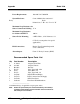
Power Requirements: 100-240 VAC 50/60 Hz
System Enclosure: Control Module fits standard 19”
Relay Rack
Dimensions: 7” H x 12.3” D x 19” W
Maximum Loop Resistance for
Sensor Connections/Cabling: 35
Maximum Loop Resistance
for 4-20 mA OUTPUT: 600
Sensor Probe Mounting: 2 MTG. Holes , 3/16” Diameter, 2 3/
8”
C-TO-C (custom probes for special
applications).
Field Connections: Barrier-Type Terminal Strips with
screw connections.
Alarm Output: Form “C” Relay Contacts (SPDT)
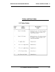
Recommended Spare Parts List
Qty Part Number Description
2 A-12698 Adapter, Flow-Thru
10 A-11091 Adapter, Female
4 B-12093 Detector
5 F-1374 Fuse, Type 3AG, 1/8A
10 F-229 Fuse, Micro, 2A
5 F-1379 Fuse, Type 3AG, 3A
1 C-65446 PCB, Front Panel Display
1 C-67479 PCB, Constant Current Supply
1 C-65446 PCB, Front Panel
1 C-66910 Front Panel With Membrane
_____________________
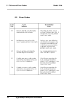
A minimum charge is applicable to spare parts orders.
Note: Orders for replacement parts should include the part number (if
available) and the model and serial number of the instrument for
which the parts are intended.
W
W