
User manual


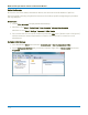


Table Of Contents
- Introduction
- Resources
- Notational Conventions
- Part 1: Making the Remote Connection
- Understanding Remote Control Layers
- Software Tools for Remote Control
- Connecting via ENET
- Connecting via USBTMC
- Connecting via GPIB
- Connecting via LSIB
- Configuring DCOM Connections
- Testing the Remote Connection
- Remote Control Assistant
- ActiveDSO
- VISA
- WaveStudio
- Part 2: Automation Programming Reference
- Automation Overview
- XStreamBrowser
- Viewing XStreamDSO Objects
- VBS Command
- Approach 1: Control from XStreamBrowser
- Approach 2: Program in VBS
- Approach 3: Program Using ActiveDSO
- Approach 4: Program Using VISA
- Control Variables
- Result Interfaces
- Synchronization
- Application Interactions
- Early and Late Binding
- Automation Programming Conventions
- Using Programming Variables
- Automation in MATLAB
- Automation in Python
- Automation in C#
- Part 3: Automation Control Variable Reference
- app
- app.Acquisition
- app.Acquisition.Cn
- app.Acquisition.Trigger
- app.Cursors
- app.CustomDSO
- app.Display
- app.Hardcopy
- app.History
- app.LabNotebook
- app.LogicAnalyzer
- app.Math
- app.Math.Fn and app.Math.XY
- app.Measure
- app.Measure.Pn
- app.Memory
- app.Memory.Mn
- app.PassFail
- app.PassFail.Qn
- app.Preferences
- app.ProbesCal
- app.SpecAnalyzer
- app.SaveRecall
- app.SaveRecall.Remote
- app.SaveRecall.Setup
- app.SaveRecall.Table
- app.SaveRecall.Utilities
- app.SaveRecall.Waveform
- app.TriggerScan
- app.Utility
- app.WaveScan
- app.WebEditor
- app.Zoom
- Part 4: Automation Result Interface Reference
- Base
- BinPopulations
- Bins
- BinWidth
- BusName
- CellType
- CellValue
- Columns
- DataArray
- ExtendedStatus
- FirstEventTime
- FirstPopulatedBin
- HorizontalFrameStart
- HorizontalFrameStop
- HorizontalOffset
- HorizontalPerColumn
- HorizontalPerStep
- HorizontalResolution
- HorizontalUnits
- HorizontalVarianceArray
- HorizontalVariances
- IndexOfFirstSampleInFrame
- LastEventTime
- LastPopulatedBin
- Levels
- LineAliasName
- LineName
- Lines
- Max
- MaxPopulation
- MaxPopulationBin
- MaxPopulationInRectangle
- Mean
- Min
- NumFrameDimensions
- NumSamplesInFrame
- OffsetAtLeftEdge
- Peaks
- PeakInfo
- PopulationInside
- PopulationOfRectangle
- PopulationOver
- PopulationUnder
- RMS
- Rows
- Samples
- Sdev
- Status
- StatusDescription
- Sweeps
- Top
- UniformInterval
- UpdateTime
- Value
- ValueArray
- VerticalFrameStart
- VerticalFrameStop
- VerticalMaxPossible
- VerticalMinPossible
- VerticalOffset
- VerticalPerRow
- VerticalPerStep
- VerticalResolution
- VerticalUnits
- XFrameStart
- XFrameStop
- XMaxPossible
- XMinPossible
- XOffset
- XPerStep
- XResolution
- XUnits
- YFrameStart
- YFrameStop
- YMaxPossible
- YMinPossible
- YOffset
- YPerStep
- YResolution
- YUnits
- Part 5: IEEE 488.2 Programming Reference
- GPIB Overview
- Interface Definitions
- IEEE 488.1 Standard Messages
- Program Message Format
- Data Types
- Response Messages
- I/O Buffers
- Making Service Requests
- Taking Instrument Polls
- Timing and Synchronization
- Waveform Transfer
- Part 6: IEEE 488.2 Command Reference
- Commands and Queries by Short Form
- Commands and Queries by Subsystem
- ACQUISITION Commands and Queries
- ARM_ACQUISITION, ARM
- AUTO_SETUP, ASET
- ATTENUATION, ATTN
- BANDWIDTH_LIMIT, BWL
- COMBINE_CHANNELS, COMB
- COUPLING, CPL
- FORCE_TRIGGER, FRTR
- INTERLEAVED, ILVD
- MEMORY_SIZE, MSIZ
- OFFSET, OFST
- REFERENCE_CLOCK, RCLK
- SAMPLE_CLOCK, SCLK
- SEQUENCE, SEQ
- STOP
- TIME_DIV, TDIV
- TRIG_COUPLING, TRCP
- TRIG_DELAY, TRDL
- *TRG
- TRIG_LEVEL, TRLV
- TRIG_MODE, TRMD
- TRIG_PATTERN, TRPA
- TRIG_SELECT, TRSE
- TRIG_SLOPE, TRSL
- VOLT_DIV, VDIV
- WAIT
- AUTOMATION Commands and Queries
- COMMUNICATION Commands and Queries
- CURSOR Commands and Queries
- DISPLAY Commands and Queries
- FUNCTION Commands and Queries
- HARDCOPY Commands and Queries
- MISCELLANEOUS Commands and Queries
- PROBE Commands
- SAVE/RECALL SETUP Commands and Queries
- STATUS Commands and Queries
- STORAGE Commands and Queries
- WAVEFORM TRANSFER Commands and Queries
- DISK DRIVE ANALYSIS (Option) Commands and Queries
- DD_ANALOG_COMP_THRESH, DACT
- DD_ANALYZE_REGION_DISABLE, DARD
- DD_ANALYZE_REGION_LENGTH, DARL
- DD_ANALYZE_REGION_START, DARS
- DD_BITCELL, DBIT
- DD_BYTE_OFFSET, DBYT
- DD_BYTE_OFFSET_SEGMENT, DSEG
- DD_CTAF_3DB, D3D
- DD_CTAF_BOOST, DBST
- DD_CTAF_FC, DDFC
- DD_CTAF_GROUP_DELAY, DFGD
- DD_ENCODING, DENC
- DD_ERR_INFO?, DERI?
- DD_ERR_NUM, DERR
- DD_FIND_BITCELL?, DFBIT?
- DD_FIND_ERROR, DFER
- DD_FIND_METHOD, DDFM
- DD_FIR, DFIR
- DD_FIR_ENABLE, DFEN
- DD_HEADSIGNAL_CHANNEL, DHSC
- DD_IGNORE_SAMPLES, DIGS
- DD_ML_MIN_SPACING, DRLM
- DD_ML_RUN_LENGTH_LIMIT, DRLE
- DD_NUM_ERRORS?, DNER?
- DD_OVERLAP_REF, DOVL
- DD_PES_ANALYSIS, DPA
- DD_PES_DATA?, DPD?
- DD_PES_SUMMARY_DATA?, DPSD?
- DD_READ_GATE_POLARITY, DRGP
- DD_READCLOCK_CHANNEL, DRCC
- DD_READGATE_CHANNEL, DRGC
- DD_RESET_AVERAGE, DRAV
- DD_SAM_THRESH, DST
- DD_SAMPLE_PHASE, DSPH
- DD_SHOW_FILTERED, DSF
- DD_SHOW_LEVELS, DSLV
- DD_SHOW_ML, DSML
- DD_SHOW_SAMPLE_TIMES, DSST
- DD_SIGNAL_INPUT, DDSI
- DD_SIGNAL_TYPE, DSIG
- DD_START_AVERAGING, DSAV
- DD_STORE_REFERENCE, DSTR
- DD_TRAIN_FILTER?, DTF?
- DD_VCO_SYNCH_PATTERN, DVSP
- DD_VCOSYNCH_TO_DATA, DVTD
- ET-PMT (Option) Commands and Queries
- Blank Page
MAUI Oscilloscopes Remote Control and Automation Manual
Testing the Remote Connection
Once you have completed all the steps required to make the remote connection to your oscilloscope, test
that you can "see" it from the controller and send remote commands.
Using WaveStudio
The free WaveStudio software is capable of testing several types of remote connection as well as serving
as a remote command terminal for controlling the oscilloscope. A trial copy is installed on the oscilloscope,
and another may be installed on Windows-based PCs. For download information, see Resources.
Follow these steps to test the connection:
1.
Click the Add Scope button on My Scope Explorer or the Scope menu ribbon.
2. On the Add Device dialog, select the remote connection type.
3. Enter the oscilloscope's network name or address and click OK.
If the oscilloscope is found, an entry is added to the My Scope Explorer window. The status should indicate
the device is "Alive." This confirms the connection is working.
If the oscilloscope is found but cannot be connected, after a brief time out an entry is added to My Scope
Explorer indicating the selected device is "Dead." Check the address and physical connection again. If you
still cannot connect, consult with your Network Administrator.
Using the PING Command
For LAN users, both the physical cable connection and proper host TCP/IP configuration can be verified
using the Ping command.
Note: PING is a good way to check the network connection, but it doesn't guarantee the socket
connection to the oscilloscope at port 1861. Connecting via WaveStudio or XStreamBrowser is a
better test.
At an MS-DOS prompt, type:
ping <IP_address>
where <IP_address> is the address assigned to the oscilloscope.
The Command Prompt window shows an exchange similar to that below if the Ping is successful. The
Ethernet connection is shown as established and the ping command has sent a message to the
instrument and waited for a response. If a timeout occurs, the IP address used for the destination (the
oscilloscope) is incorrect or not within the subnet mask of the host's IP.
1-20