
User manual


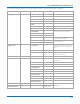
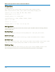

Table Of Contents
- Introduction
- Resources
- Notational Conventions
- Part 1: Making the Remote Connection
- Understanding Remote Control Layers
- Software Tools for Remote Control
- Connecting via ENET
- Connecting via USBTMC
- Connecting via GPIB
- Connecting via LSIB
- Configuring DCOM Connections
- Testing the Remote Connection
- Remote Control Assistant
- ActiveDSO
- VISA
- WaveStudio
- Part 2: Automation Programming Reference
- Automation Overview
- XStreamBrowser
- Viewing XStreamDSO Objects
- VBS Command
- Approach 1: Control from XStreamBrowser
- Approach 2: Program in VBS
- Approach 3: Program Using ActiveDSO
- Approach 4: Program Using VISA
- Control Variables
- Result Interfaces
- Synchronization
- Application Interactions
- Early and Late Binding
- Automation Programming Conventions
- Using Programming Variables
- Automation in MATLAB
- Automation in Python
- Automation in C#
- Part 3: Automation Control Variable Reference
- app
- app.Acquisition
- app.Acquisition.Cn
- app.Acquisition.Trigger
- app.Cursors
- app.CustomDSO
- app.Display
- app.Hardcopy
- app.History
- app.LabNotebook
- app.LogicAnalyzer
- app.Math
- app.Math.Fn and app.Math.XY
- app.Measure
- app.Measure.Pn
- app.Memory
- app.Memory.Mn
- app.PassFail
- app.PassFail.Qn
- app.Preferences
- app.ProbesCal
- app.SpecAnalyzer
- app.SaveRecall
- app.SaveRecall.Remote
- app.SaveRecall.Setup
- app.SaveRecall.Table
- app.SaveRecall.Utilities
- app.SaveRecall.Waveform
- app.TriggerScan
- app.Utility
- app.WaveScan
- app.WebEditor
- app.Zoom
- Part 4: Automation Result Interface Reference
- Base
- BinPopulations
- Bins
- BinWidth
- BusName
- CellType
- CellValue
- Columns
- DataArray
- ExtendedStatus
- FirstEventTime
- FirstPopulatedBin
- HorizontalFrameStart
- HorizontalFrameStop
- HorizontalOffset
- HorizontalPerColumn
- HorizontalPerStep
- HorizontalResolution
- HorizontalUnits
- HorizontalVarianceArray
- HorizontalVariances
- IndexOfFirstSampleInFrame
- LastEventTime
- LastPopulatedBin
- Levels
- LineAliasName
- LineName
- Lines
- Max
- MaxPopulation
- MaxPopulationBin
- MaxPopulationInRectangle
- Mean
- Min
- NumFrameDimensions
- NumSamplesInFrame
- OffsetAtLeftEdge
- Peaks
- PeakInfo
- PopulationInside
- PopulationOfRectangle
- PopulationOver
- PopulationUnder
- RMS
- Rows
- Samples
- Sdev
- Status
- StatusDescription
- Sweeps
- Top
- UniformInterval
- UpdateTime
- Value
- ValueArray
- VerticalFrameStart
- VerticalFrameStop
- VerticalMaxPossible
- VerticalMinPossible
- VerticalOffset
- VerticalPerRow
- VerticalPerStep
- VerticalResolution
- VerticalUnits
- XFrameStart
- XFrameStop
- XMaxPossible
- XMinPossible
- XOffset
- XPerStep
- XResolution
- XUnits
- YFrameStart
- YFrameStop
- YMaxPossible
- YMinPossible
- YOffset
- YPerStep
- YResolution
- YUnits
- Part 5: IEEE 488.2 Programming Reference
- GPIB Overview
- Interface Definitions
- IEEE 488.1 Standard Messages
- Program Message Format
- Data Types
- Response Messages
- I/O Buffers
- Making Service Requests
- Taking Instrument Polls
- Timing and Synchronization
- Waveform Transfer
- Part 6: IEEE 488.2 Command Reference
- Commands and Queries by Short Form
- Commands and Queries by Subsystem
- ACQUISITION Commands and Queries
- ARM_ACQUISITION, ARM
- AUTO_SETUP, ASET
- ATTENUATION, ATTN
- BANDWIDTH_LIMIT, BWL
- COMBINE_CHANNELS, COMB
- COUPLING, CPL
- FORCE_TRIGGER, FRTR
- INTERLEAVED, ILVD
- MEMORY_SIZE, MSIZ
- OFFSET, OFST
- REFERENCE_CLOCK, RCLK
- SAMPLE_CLOCK, SCLK
- SEQUENCE, SEQ
- STOP
- TIME_DIV, TDIV
- TRIG_COUPLING, TRCP
- TRIG_DELAY, TRDL
- *TRG
- TRIG_LEVEL, TRLV
- TRIG_MODE, TRMD
- TRIG_PATTERN, TRPA
- TRIG_SELECT, TRSE
- TRIG_SLOPE, TRSL
- VOLT_DIV, VDIV
- WAIT
- AUTOMATION Commands and Queries
- COMMUNICATION Commands and Queries
- CURSOR Commands and Queries
- DISPLAY Commands and Queries
- FUNCTION Commands and Queries
- HARDCOPY Commands and Queries
- MISCELLANEOUS Commands and Queries
- PROBE Commands
- SAVE/RECALL SETUP Commands and Queries
- STATUS Commands and Queries
- STORAGE Commands and Queries
- WAVEFORM TRANSFER Commands and Queries
- DISK DRIVE ANALYSIS (Option) Commands and Queries
- DD_ANALOG_COMP_THRESH, DACT
- DD_ANALYZE_REGION_DISABLE, DARD
- DD_ANALYZE_REGION_LENGTH, DARL
- DD_ANALYZE_REGION_START, DARS
- DD_BITCELL, DBIT
- DD_BYTE_OFFSET, DBYT
- DD_BYTE_OFFSET_SEGMENT, DSEG
- DD_CTAF_3DB, D3D
- DD_CTAF_BOOST, DBST
- DD_CTAF_FC, DDFC
- DD_CTAF_GROUP_DELAY, DFGD
- DD_ENCODING, DENC
- DD_ERR_INFO?, DERI?
- DD_ERR_NUM, DERR
- DD_FIND_BITCELL?, DFBIT?
- DD_FIND_ERROR, DFER
- DD_FIND_METHOD, DDFM
- DD_FIR, DFIR
- DD_FIR_ENABLE, DFEN
- DD_HEADSIGNAL_CHANNEL, DHSC
- DD_IGNORE_SAMPLES, DIGS
- DD_ML_MIN_SPACING, DRLM
- DD_ML_RUN_LENGTH_LIMIT, DRLE
- DD_NUM_ERRORS?, DNER?
- DD_OVERLAP_REF, DOVL
- DD_PES_ANALYSIS, DPA
- DD_PES_DATA?, DPD?
- DD_PES_SUMMARY_DATA?, DPSD?
- DD_READ_GATE_POLARITY, DRGP
- DD_READCLOCK_CHANNEL, DRCC
- DD_READGATE_CHANNEL, DRGC
- DD_RESET_AVERAGE, DRAV
- DD_SAM_THRESH, DST
- DD_SAMPLE_PHASE, DSPH
- DD_SHOW_FILTERED, DSF
- DD_SHOW_LEVELS, DSLV
- DD_SHOW_ML, DSML
- DD_SHOW_SAMPLE_TIMES, DSST
- DD_SIGNAL_INPUT, DDSI
- DD_SIGNAL_TYPE, DSIG
- DD_START_AVERAGING, DSAV
- DD_STORE_REFERENCE, DSTR
- DD_TRAIN_FILTER?, DTF?
- DD_VCO_SYNCH_PATTERN, DVSP
- DD_VCOSYNCH_TO_DATA, DVTD
- ET-PMT (Option) Commands and Queries
- Blank Page

MAUI Oscilloscopes Remote Control and Automation Manual
TV Trigger Syntax
TV trigger syntax is:
TRIG_SELECT TV,SR,<source>,FLDC,<field_count>,FLD,<trigger_field>,
CHAR,<characteristics>,LPIC,<lpic>,ILAC,<ilace>,LINE,<trigger_line>
<source>:= <C1 to Cn, LINE, EX, EX5, EX10, ETM10>
<field_count>:= {1, 2, 4, 8}
<trigger_field>:= 1 to field_count
<characteristics>:= {NTSC, PALSEC, CUST50, CUST60}
<lpic>:= 1 to 1500
<ilace>:= {1, 2, 4, 8}
<trigger_line>:= 1 to 1500, or 0 for any line
DDA Trigger Syntax
DDA models and oscilloscopes with the DDA software option installed include the following disk drive
analysis trigger types:
Read Gate Trigger
TRIG_SELECT READ,SR,<read gate source>,WIDTH,<min. read gate pulse width>
Sector Pulse Trigger
TRIG_SELECT SECTOR,SR,<sector source>,QL,<index source>NUM,<sector number>
Servo Gate Trigger
TRIG_SELECT SERVO,SR,<servo gate source>,QL,<index source>,FIRST,<servo burst after
index for first trigger>,SKIP,<skip number of bursts before next trigger>
PES Window Trigger
TRIG_SELECT PESWIN,SR,<PES source>,QL,<servo gate source>,WINDOW,<window size>
See the DDA Reference Manual for more information about the operation of these triggers.
6-38