
User manual


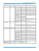

Table Of Contents
- Introduction
- Resources
- Notational Conventions
- Part 1: Making the Remote Connection
- Understanding Remote Control Layers
- Software Tools for Remote Control
- Connecting via ENET
- Connecting via USBTMC
- Connecting via GPIB
- Connecting via LSIB
- Configuring DCOM Connections
- Testing the Remote Connection
- Remote Control Assistant
- ActiveDSO
- VISA
- WaveStudio
- Part 2: Automation Programming Reference
- Automation Overview
- XStreamBrowser
- Viewing XStreamDSO Objects
- VBS Command
- Approach 1: Control from XStreamBrowser
- Approach 2: Program in VBS
- Approach 3: Program Using ActiveDSO
- Approach 4: Program Using VISA
- Control Variables
- Result Interfaces
- Synchronization
- Application Interactions
- Early and Late Binding
- Automation Programming Conventions
- Using Programming Variables
- Automation in MATLAB
- Automation in Python
- Automation in C#
- Part 3: Automation Control Variable Reference
- app
- app.Acquisition
- app.Acquisition.Cn
- app.Acquisition.Trigger
- app.Cursors
- app.CustomDSO
- app.Display
- app.Hardcopy
- app.History
- app.LabNotebook
- app.LogicAnalyzer
- app.Math
- app.Math.Fn and app.Math.XY
- app.Measure
- app.Measure.Pn
- app.Memory
- app.Memory.Mn
- app.PassFail
- app.PassFail.Qn
- app.Preferences
- app.ProbesCal
- app.SpecAnalyzer
- app.SaveRecall
- app.SaveRecall.Remote
- app.SaveRecall.Setup
- app.SaveRecall.Table
- app.SaveRecall.Utilities
- app.SaveRecall.Waveform
- app.TriggerScan
- app.Utility
- app.WaveScan
- app.WebEditor
- app.Zoom
- Part 4: Automation Result Interface Reference
- Base
- BinPopulations
- Bins
- BinWidth
- BusName
- CellType
- CellValue
- Columns
- DataArray
- ExtendedStatus
- FirstEventTime
- FirstPopulatedBin
- HorizontalFrameStart
- HorizontalFrameStop
- HorizontalOffset
- HorizontalPerColumn
- HorizontalPerStep
- HorizontalResolution
- HorizontalUnits
- HorizontalVarianceArray
- HorizontalVariances
- IndexOfFirstSampleInFrame
- LastEventTime
- LastPopulatedBin
- Levels
- LineAliasName
- LineName
- Lines
- Max
- MaxPopulation
- MaxPopulationBin
- MaxPopulationInRectangle
- Mean
- Min
- NumFrameDimensions
- NumSamplesInFrame
- OffsetAtLeftEdge
- Peaks
- PeakInfo
- PopulationInside
- PopulationOfRectangle
- PopulationOver
- PopulationUnder
- RMS
- Rows
- Samples
- Sdev
- Status
- StatusDescription
- Sweeps
- Top
- UniformInterval
- UpdateTime
- Value
- ValueArray
- VerticalFrameStart
- VerticalFrameStop
- VerticalMaxPossible
- VerticalMinPossible
- VerticalOffset
- VerticalPerRow
- VerticalPerStep
- VerticalResolution
- VerticalUnits
- XFrameStart
- XFrameStop
- XMaxPossible
- XMinPossible
- XOffset
- XPerStep
- XResolution
- XUnits
- YFrameStart
- YFrameStop
- YMaxPossible
- YMinPossible
- YOffset
- YPerStep
- YResolution
- YUnits
- Part 5: IEEE 488.2 Programming Reference
- GPIB Overview
- Interface Definitions
- IEEE 488.1 Standard Messages
- Program Message Format
- Data Types
- Response Messages
- I/O Buffers
- Making Service Requests
- Taking Instrument Polls
- Timing and Synchronization
- Waveform Transfer
- Part 6: IEEE 488.2 Command Reference
- Commands and Queries by Short Form
- Commands and Queries by Subsystem
- ACQUISITION Commands and Queries
- ARM_ACQUISITION, ARM
- AUTO_SETUP, ASET
- ATTENUATION, ATTN
- BANDWIDTH_LIMIT, BWL
- COMBINE_CHANNELS, COMB
- COUPLING, CPL
- FORCE_TRIGGER, FRTR
- INTERLEAVED, ILVD
- MEMORY_SIZE, MSIZ
- OFFSET, OFST
- REFERENCE_CLOCK, RCLK
- SAMPLE_CLOCK, SCLK
- SEQUENCE, SEQ
- STOP
- TIME_DIV, TDIV
- TRIG_COUPLING, TRCP
- TRIG_DELAY, TRDL
- *TRG
- TRIG_LEVEL, TRLV
- TRIG_MODE, TRMD
- TRIG_PATTERN, TRPA
- TRIG_SELECT, TRSE
- TRIG_SLOPE, TRSL
- VOLT_DIV, VDIV
- WAIT
- AUTOMATION Commands and Queries
- COMMUNICATION Commands and Queries
- CURSOR Commands and Queries
- DISPLAY Commands and Queries
- FUNCTION Commands and Queries
- HARDCOPY Commands and Queries
- MISCELLANEOUS Commands and Queries
- PROBE Commands
- SAVE/RECALL SETUP Commands and Queries
- STATUS Commands and Queries
- STORAGE Commands and Queries
- WAVEFORM TRANSFER Commands and Queries
- DISK DRIVE ANALYSIS (Option) Commands and Queries
- DD_ANALOG_COMP_THRESH, DACT
- DD_ANALYZE_REGION_DISABLE, DARD
- DD_ANALYZE_REGION_LENGTH, DARL
- DD_ANALYZE_REGION_START, DARS
- DD_BITCELL, DBIT
- DD_BYTE_OFFSET, DBYT
- DD_BYTE_OFFSET_SEGMENT, DSEG
- DD_CTAF_3DB, D3D
- DD_CTAF_BOOST, DBST
- DD_CTAF_FC, DDFC
- DD_CTAF_GROUP_DELAY, DFGD
- DD_ENCODING, DENC
- DD_ERR_INFO?, DERI?
- DD_ERR_NUM, DERR
- DD_FIND_BITCELL?, DFBIT?
- DD_FIND_ERROR, DFER
- DD_FIND_METHOD, DDFM
- DD_FIR, DFIR
- DD_FIR_ENABLE, DFEN
- DD_HEADSIGNAL_CHANNEL, DHSC
- DD_IGNORE_SAMPLES, DIGS
- DD_ML_MIN_SPACING, DRLM
- DD_ML_RUN_LENGTH_LIMIT, DRLE
- DD_NUM_ERRORS?, DNER?
- DD_OVERLAP_REF, DOVL
- DD_PES_ANALYSIS, DPA
- DD_PES_DATA?, DPD?
- DD_PES_SUMMARY_DATA?, DPSD?
- DD_READ_GATE_POLARITY, DRGP
- DD_READCLOCK_CHANNEL, DRCC
- DD_READGATE_CHANNEL, DRGC
- DD_RESET_AVERAGE, DRAV
- DD_SAM_THRESH, DST
- DD_SAMPLE_PHASE, DSPH
- DD_SHOW_FILTERED, DSF
- DD_SHOW_LEVELS, DSLV
- DD_SHOW_ML, DSML
- DD_SHOW_SAMPLE_TIMES, DSST
- DD_SIGNAL_INPUT, DDSI
- DD_SIGNAL_TYPE, DSIG
- DD_START_AVERAGING, DSAV
- DD_STORE_REFERENCE, DSTR
- DD_TRAIN_FILTER?, DTF?
- DD_VCO_SYNCH_PATTERN, DVSP
- DD_VCOSYNCH_TO_DATA, DVTD
- ET-PMT (Option) Commands and Queries
- Blank Page

MAUI Oscilloscopes Remote Control and Automation Manual
TRIG_SELECT, TRSE
Description
The TRIG_SELECT command selects the conditions that trigger the acquisition of waveforms. Depending
on the trigger type, additional parameters may need to be specified. These additional parameters are
grouped in pairs. The first in the pair names the variable for modification, while the second gives the new
value for assignment. Pairs may be given in any order and restricted only to the variables to be changed.
The oscilloscope interprets the "Hold Type" (HT) parameter as instruction to hold the trigger for a given
amount of time or number of events, or until a certain trigger source or qualifier source condition is
achieved (e.g., a pulse of a given width). The "Hold Value" (HV) parameter provides the value that satisfies
the HT condition; they are always used together.
State Qualified and Edge Qualified triggers should use the Qualifier Source (QL) parameter and include any
HT conditions to be observed on the qualifying signal.
The level used for the Edge and Edge Qualified trigger types is supplied with the TRIG_LEVEL command,
and the slope with the TRIG_SLOPE command. These are not set using the HT parameter.
To set logic pattern triggers, use the Automation commands or the GPIB command TRIG_PATTERN. The
receipt of the TRIG_PATTERN command overrides the TRIG_SELECT settings until another TRIG_SELECT
is sent.
Use the Automation commands to set any trigger not shown here. See the product datasheet for the
triggers supported by your model.
Command Syntax
For all but the TV trigger, the command syntax for standard triggers is:
TRIG_SELECT <trig_type>,SR,<source>[,QL,<source>,HT,<hold_type>,HV,<hold_
value>,HV2,<hold value>]
See table below for valid parameter values.
The trigger sources available depend on your oscilloscope model. See the product datasheet for
specifications.
When specifying <hold_value>, the unit S (seconds) is optional; other units should be specified using the
notation shown in Units and Multipliers.
6-36