
User manual


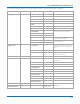
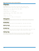
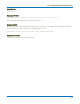

Table Of Contents
- Introduction
- Resources
- Notational Conventions
- Part 1: Making the Remote Connection
- Understanding Remote Control Layers
- Software Tools for Remote Control
- Connecting via ENET
- Connecting via USBTMC
- Connecting via GPIB
- Connecting via LSIB
- Configuring DCOM Connections
- Testing the Remote Connection
- Remote Control Assistant
- ActiveDSO
- VISA
- WaveStudio
- Part 2: Automation Programming Reference
- Automation Overview
- XStreamBrowser
- Viewing XStreamDSO Objects
- VBS Command
- Approach 1: Control from XStreamBrowser
- Approach 2: Program in VBS
- Approach 3: Program Using ActiveDSO
- Approach 4: Program Using VISA
- Control Variables
- Result Interfaces
- Synchronization
- Application Interactions
- Early and Late Binding
- Automation Programming Conventions
- Using Programming Variables
- Automation in MATLAB
- Automation in Python
- Automation in C#
- Part 3: Automation Control Variable Reference
- app
- app.Acquisition
- app.Acquisition.Cn
- app.Acquisition.Trigger
- app.Cursors
- app.CustomDSO
- app.Display
- app.Hardcopy
- app.History
- app.LabNotebook
- app.LogicAnalyzer
- app.Math
- app.Math.Fn and app.Math.XY
- app.Measure
- app.Measure.Pn
- app.Memory
- app.Memory.Mn
- app.PassFail
- app.PassFail.Qn
- app.Preferences
- app.ProbesCal
- app.SpecAnalyzer
- app.SaveRecall
- app.SaveRecall.Remote
- app.SaveRecall.Setup
- app.SaveRecall.Table
- app.SaveRecall.Utilities
- app.SaveRecall.Waveform
- app.TriggerScan
- app.Utility
- app.WaveScan
- app.WebEditor
- app.Zoom
- Part 4: Automation Result Interface Reference
- Base
- BinPopulations
- Bins
- BinWidth
- BusName
- CellType
- CellValue
- Columns
- DataArray
- ExtendedStatus
- FirstEventTime
- FirstPopulatedBin
- HorizontalFrameStart
- HorizontalFrameStop
- HorizontalOffset
- HorizontalPerColumn
- HorizontalPerStep
- HorizontalResolution
- HorizontalUnits
- HorizontalVarianceArray
- HorizontalVariances
- IndexOfFirstSampleInFrame
- LastEventTime
- LastPopulatedBin
- Levels
- LineAliasName
- LineName
- Lines
- Max
- MaxPopulation
- MaxPopulationBin
- MaxPopulationInRectangle
- Mean
- Min
- NumFrameDimensions
- NumSamplesInFrame
- OffsetAtLeftEdge
- Peaks
- PeakInfo
- PopulationInside
- PopulationOfRectangle
- PopulationOver
- PopulationUnder
- RMS
- Rows
- Samples
- Sdev
- Status
- StatusDescription
- Sweeps
- Top
- UniformInterval
- UpdateTime
- Value
- ValueArray
- VerticalFrameStart
- VerticalFrameStop
- VerticalMaxPossible
- VerticalMinPossible
- VerticalOffset
- VerticalPerRow
- VerticalPerStep
- VerticalResolution
- VerticalUnits
- XFrameStart
- XFrameStop
- XMaxPossible
- XMinPossible
- XOffset
- XPerStep
- XResolution
- XUnits
- YFrameStart
- YFrameStop
- YMaxPossible
- YMinPossible
- YOffset
- YPerStep
- YResolution
- YUnits
- Part 5: IEEE 488.2 Programming Reference
- GPIB Overview
- Interface Definitions
- IEEE 488.1 Standard Messages
- Program Message Format
- Data Types
- Response Messages
- I/O Buffers
- Making Service Requests
- Taking Instrument Polls
- Timing and Synchronization
- Waveform Transfer
- Part 6: IEEE 488.2 Command Reference
- Commands and Queries by Short Form
- Commands and Queries by Subsystem
- ACQUISITION Commands and Queries
- ARM_ACQUISITION, ARM
- AUTO_SETUP, ASET
- ATTENUATION, ATTN
- BANDWIDTH_LIMIT, BWL
- COMBINE_CHANNELS, COMB
- COUPLING, CPL
- FORCE_TRIGGER, FRTR
- INTERLEAVED, ILVD
- MEMORY_SIZE, MSIZ
- OFFSET, OFST
- REFERENCE_CLOCK, RCLK
- SAMPLE_CLOCK, SCLK
- SEQUENCE, SEQ
- STOP
- TIME_DIV, TDIV
- TRIG_COUPLING, TRCP
- TRIG_DELAY, TRDL
- *TRG
- TRIG_LEVEL, TRLV
- TRIG_MODE, TRMD
- TRIG_PATTERN, TRPA
- TRIG_SELECT, TRSE
- TRIG_SLOPE, TRSL
- VOLT_DIV, VDIV
- WAIT
- AUTOMATION Commands and Queries
- COMMUNICATION Commands and Queries
- CURSOR Commands and Queries
- DISPLAY Commands and Queries
- FUNCTION Commands and Queries
- HARDCOPY Commands and Queries
- MISCELLANEOUS Commands and Queries
- PROBE Commands
- SAVE/RECALL SETUP Commands and Queries
- STATUS Commands and Queries
- STORAGE Commands and Queries
- WAVEFORM TRANSFER Commands and Queries
- DISK DRIVE ANALYSIS (Option) Commands and Queries
- DD_ANALOG_COMP_THRESH, DACT
- DD_ANALYZE_REGION_DISABLE, DARD
- DD_ANALYZE_REGION_LENGTH, DARL
- DD_ANALYZE_REGION_START, DARS
- DD_BITCELL, DBIT
- DD_BYTE_OFFSET, DBYT
- DD_BYTE_OFFSET_SEGMENT, DSEG
- DD_CTAF_3DB, D3D
- DD_CTAF_BOOST, DBST
- DD_CTAF_FC, DDFC
- DD_CTAF_GROUP_DELAY, DFGD
- DD_ENCODING, DENC
- DD_ERR_INFO?, DERI?
- DD_ERR_NUM, DERR
- DD_FIND_BITCELL?, DFBIT?
- DD_FIND_ERROR, DFER
- DD_FIND_METHOD, DDFM
- DD_FIR, DFIR
- DD_FIR_ENABLE, DFEN
- DD_HEADSIGNAL_CHANNEL, DHSC
- DD_IGNORE_SAMPLES, DIGS
- DD_ML_MIN_SPACING, DRLM
- DD_ML_RUN_LENGTH_LIMIT, DRLE
- DD_NUM_ERRORS?, DNER?
- DD_OVERLAP_REF, DOVL
- DD_PES_ANALYSIS, DPA
- DD_PES_DATA?, DPD?
- DD_PES_SUMMARY_DATA?, DPSD?
- DD_READ_GATE_POLARITY, DRGP
- DD_READCLOCK_CHANNEL, DRCC
- DD_READGATE_CHANNEL, DRGC
- DD_RESET_AVERAGE, DRAV
- DD_SAM_THRESH, DST
- DD_SAMPLE_PHASE, DSPH
- DD_SHOW_FILTERED, DSF
- DD_SHOW_LEVELS, DSLV
- DD_SHOW_ML, DSML
- DD_SHOW_SAMPLE_TIMES, DSST
- DD_SIGNAL_INPUT, DDSI
- DD_SIGNAL_TYPE, DSIG
- DD_START_AVERAGING, DSAV
- DD_STORE_REFERENCE, DSTR
- DD_TRAIN_FILTER?, DTF?
- DD_VCO_SYNCH_PATTERN, DVSP
- DD_VCOSYNCH_TO_DATA, DVTD
- ET-PMT (Option) Commands and Queries
- Blank Page

Part 6: IEEE 488.2 Command Reference
TRIG_DELAY, TRDL
Description
The TRIG_DELAY command sets the time at which the trigger is to occur with respect to the nominal zero
delay position, which defaults to the center of the grid. This is also referred to as Horizontal Delay.
The response to the TRIG_DELAY? query indicates the trigger time with respect to the first acquired data
point. Setting a trigger delay value of zero places the trigger indicator at the center of the grid.
Note: MAUI oscilloscopes support programming the trigger delay in units of time; the legacy
argument PCT (of grid) is no longer supported. Positive values move the trigger position to the
right of the nominal zero delay position, and increase the portion of the waveform before the
trigger point. Negative values move the trigger point in the opposite direction.
Command Syntax
TRIG_DELAY <value>
The <value> is given in time and may be anywhere in the ranges:
Negative delay: ( 0 to -10,000) x Time/div
Postive delay: (0 to +10) x Time/div
If a value outside these ranges is specified, the trigger time is set to the nearest limit and the VAB bit (bit 2)
is set in the STB register.
Query Syntax
TRIG_DELAY?
Response Format
TRIG_DELAY <value>
Example (GPIB)
The following instruction sets a post-trigger delay of -20 S:
CMD$="TRDL -20S": CALL IBWRT(SCOPE%,CMD$)
Related Commands
TIME_DIV, TRIG_COUPLING, TRIG_LEVEL, TRIG_MODE, TRIG_SELECT, TRIG_SLOPE
6-31