
User manual


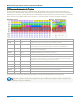


Table Of Contents
- Introduction
- Resources
- Notational Conventions
- Part 1: Making the Remote Connection
- Understanding Remote Control Layers
- Software Tools for Remote Control
- Connecting via ENET
- Connecting via USBTMC
- Connecting via GPIB
- Connecting via LSIB
- Configuring DCOM Connections
- Testing the Remote Connection
- Remote Control Assistant
- ActiveDSO
- VISA
- WaveStudio
- Part 2: Automation Programming Reference
- Automation Overview
- XStreamBrowser
- Viewing XStreamDSO Objects
- VBS Command
- Approach 1: Control from XStreamBrowser
- Approach 2: Program in VBS
- Approach 3: Program Using ActiveDSO
- Approach 4: Program Using VISA
- Control Variables
- Result Interfaces
- Synchronization
- Application Interactions
- Early and Late Binding
- Automation Programming Conventions
- Using Programming Variables
- Automation in MATLAB
- Automation in Python
- Automation in C#
- Part 3: Automation Control Variable Reference
- app
- app.Acquisition
- app.Acquisition.Cn
- app.Acquisition.Trigger
- app.Cursors
- app.CustomDSO
- app.Display
- app.Hardcopy
- app.History
- app.LabNotebook
- app.LogicAnalyzer
- app.Math
- app.Math.Fn and app.Math.XY
- app.Measure
- app.Measure.Pn
- app.Memory
- app.Memory.Mn
- app.PassFail
- app.PassFail.Qn
- app.Preferences
- app.ProbesCal
- app.SpecAnalyzer
- app.SaveRecall
- app.SaveRecall.Remote
- app.SaveRecall.Setup
- app.SaveRecall.Table
- app.SaveRecall.Utilities
- app.SaveRecall.Waveform
- app.TriggerScan
- app.Utility
- app.WaveScan
- app.WebEditor
- app.Zoom
- Part 4: Automation Result Interface Reference
- Base
- BinPopulations
- Bins
- BinWidth
- BusName
- CellType
- CellValue
- Columns
- DataArray
- ExtendedStatus
- FirstEventTime
- FirstPopulatedBin
- HorizontalFrameStart
- HorizontalFrameStop
- HorizontalOffset
- HorizontalPerColumn
- HorizontalPerStep
- HorizontalResolution
- HorizontalUnits
- HorizontalVarianceArray
- HorizontalVariances
- IndexOfFirstSampleInFrame
- LastEventTime
- LastPopulatedBin
- Levels
- LineAliasName
- LineName
- Lines
- Max
- MaxPopulation
- MaxPopulationBin
- MaxPopulationInRectangle
- Mean
- Min
- NumFrameDimensions
- NumSamplesInFrame
- OffsetAtLeftEdge
- Peaks
- PeakInfo
- PopulationInside
- PopulationOfRectangle
- PopulationOver
- PopulationUnder
- RMS
- Rows
- Samples
- Sdev
- Status
- StatusDescription
- Sweeps
- Top
- UniformInterval
- UpdateTime
- Value
- ValueArray
- VerticalFrameStart
- VerticalFrameStop
- VerticalMaxPossible
- VerticalMinPossible
- VerticalOffset
- VerticalPerRow
- VerticalPerStep
- VerticalResolution
- VerticalUnits
- XFrameStart
- XFrameStop
- XMaxPossible
- XMinPossible
- XOffset
- XPerStep
- XResolution
- XUnits
- YFrameStart
- YFrameStop
- YMaxPossible
- YMinPossible
- YOffset
- YPerStep
- YResolution
- YUnits
- Part 5: IEEE 488.2 Programming Reference
- GPIB Overview
- Interface Definitions
- IEEE 488.1 Standard Messages
- Program Message Format
- Data Types
- Response Messages
- I/O Buffers
- Making Service Requests
- Taking Instrument Polls
- Timing and Synchronization
- Waveform Transfer
- Part 6: IEEE 488.2 Command Reference
- Commands and Queries by Short Form
- Commands and Queries by Subsystem
- ACQUISITION Commands and Queries
- ARM_ACQUISITION, ARM
- AUTO_SETUP, ASET
- ATTENUATION, ATTN
- BANDWIDTH_LIMIT, BWL
- COMBINE_CHANNELS, COMB
- COUPLING, CPL
- FORCE_TRIGGER, FRTR
- INTERLEAVED, ILVD
- MEMORY_SIZE, MSIZ
- OFFSET, OFST
- REFERENCE_CLOCK, RCLK
- SAMPLE_CLOCK, SCLK
- SEQUENCE, SEQ
- STOP
- TIME_DIV, TDIV
- TRIG_COUPLING, TRCP
- TRIG_DELAY, TRDL
- *TRG
- TRIG_LEVEL, TRLV
- TRIG_MODE, TRMD
- TRIG_PATTERN, TRPA
- TRIG_SELECT, TRSE
- TRIG_SLOPE, TRSL
- VOLT_DIV, VDIV
- WAIT
- AUTOMATION Commands and Queries
- COMMUNICATION Commands and Queries
- CURSOR Commands and Queries
- DISPLAY Commands and Queries
- FUNCTION Commands and Queries
- HARDCOPY Commands and Queries
- MISCELLANEOUS Commands and Queries
- PROBE Commands
- SAVE/RECALL SETUP Commands and Queries
- STATUS Commands and Queries
- STORAGE Commands and Queries
- WAVEFORM TRANSFER Commands and Queries
- DISK DRIVE ANALYSIS (Option) Commands and Queries
- DD_ANALOG_COMP_THRESH, DACT
- DD_ANALYZE_REGION_DISABLE, DARD
- DD_ANALYZE_REGION_LENGTH, DARL
- DD_ANALYZE_REGION_START, DARS
- DD_BITCELL, DBIT
- DD_BYTE_OFFSET, DBYT
- DD_BYTE_OFFSET_SEGMENT, DSEG
- DD_CTAF_3DB, D3D
- DD_CTAF_BOOST, DBST
- DD_CTAF_FC, DDFC
- DD_CTAF_GROUP_DELAY, DFGD
- DD_ENCODING, DENC
- DD_ERR_INFO?, DERI?
- DD_ERR_NUM, DERR
- DD_FIND_BITCELL?, DFBIT?
- DD_FIND_ERROR, DFER
- DD_FIND_METHOD, DDFM
- DD_FIR, DFIR
- DD_FIR_ENABLE, DFEN
- DD_HEADSIGNAL_CHANNEL, DHSC
- DD_IGNORE_SAMPLES, DIGS
- DD_ML_MIN_SPACING, DRLM
- DD_ML_RUN_LENGTH_LIMIT, DRLE
- DD_NUM_ERRORS?, DNER?
- DD_OVERLAP_REF, DOVL
- DD_PES_ANALYSIS, DPA
- DD_PES_DATA?, DPD?
- DD_PES_SUMMARY_DATA?, DPSD?
- DD_READ_GATE_POLARITY, DRGP
- DD_READCLOCK_CHANNEL, DRCC
- DD_READGATE_CHANNEL, DRGC
- DD_RESET_AVERAGE, DRAV
- DD_SAM_THRESH, DST
- DD_SAMPLE_PHASE, DSPH
- DD_SHOW_FILTERED, DSF
- DD_SHOW_LEVELS, DSLV
- DD_SHOW_ML, DSML
- DD_SHOW_SAMPLE_TIMES, DSST
- DD_SIGNAL_INPUT, DDSI
- DD_SIGNAL_TYPE, DSIG
- DD_START_AVERAGING, DSAV
- DD_STORE_REFERENCE, DSTR
- DD_TRAIN_FILTER?, DTF?
- DD_VCO_SYNCH_PATTERN, DVSP
- DD_VCOSYNCH_TO_DATA, DVTD
- ET-PMT (Option) Commands and Queries
- Blank Page

Part 5: IEEE 488.2 Programming Reference
In a way not following the byte boundaries, bits are then segregated as follows:
31, 30, 29 . . . . . . . . . . . . . . .24, 23, 22, 21 . . . . . . . . . . . . . . . . . 2, 1, 0
sign exponent bits . . . . . . . fractional bits . . . . . . . . . . . . . . . . bit 0.5, 0.25, 0.125 . . .
The sign bit s is 1 for a negative number and 0 for a positive number, so it is easy to construct the sign from
this:
S = (-1)^s
The eight exponent bits have the following values:
Bit 23 is worth 1, bit 24 is worth 2 . . . bit 29àis worth 64, bit 30 is worth 128, so the resulting number can
range from 0 to 28 -1, which is 255.
127 is then subtracted from this value e creating a range from -127 to +128. This is then used as an
exponent to raise two to a power that is 2^e, to create a value E.
Then we have to create the multiplying number. The values of the 23 bits are as follows:
Bit 22 is worth 0.5, 21 is worth 0.25, 20 is worth 0.125, 19 is worth 0.0625 . . . .
When all the bits are added together, we obtain a positive number f that can be very close to one, differing
from it only by the value of the smallest bit, if all the bits are ones. (Generally the value will be much less
than one.) Then we add one to the result, obtaining 1 + f = F. The use of the added one extends the
dynamic range of the data. Another way of calculating f is to take the 23-bit number at face value, and
divide it by 2^24.
Finally we multiply together the sign, the value E, and the value F to create the final result:
Result = (-1)^s x 2^(e-127) x (1 + f) = S x E x F
5-25