
User Manual


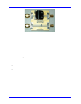
Table Of Contents
- Introduction TO QPHY-DDR3
- Signals measured
- DDR3 MEASUREMENT PREPARation
- Basic Functionality
- Using Qualiphy DDR3
- QualiPHY Compliance Test Platform
- QPHY-DDR3 Test Configurations
- 1) Clock tests DDR3-1333 (1 Probe)
- 2) CKdiff-DQse-DQSdiff 1333 Write Burst (3 Probes)
- 3) CKdiff-DQse-DQSdiff 1333 Read Burst (3 Probes)
- 4) Eye Diagram (3 Probes Debug)
- 5) Eye Diagram with CS Enabled (4 Probes Debug)
- 6) CKDiff-DQse-DQS-ADD/CTRLse (4 Probes Debug)
- 7) CKdiff-DQse-DQSp-DQsn (4 probes test, each DQS signal probed single ended)
- 8) CKp-CKn-DQse-DQSdiff (4 probe test, each CK signal is probed single ended)
- 9) Vref tests
- D1) Demo of All Tests
- QPHY-DDR3 Variables
- QPHY-DDR3 Limit Sets
- QPHY-DDR3 Tests
- Clock Tests
- tCK(avg), Average Clock Period
- tCK(abs), Absolute Clock Period
- tCH(avg), Average High Pulse Width
- tCL(avg), Average Low Pulse Width
- tCH(abs), Absolute High Pulse Width
- tCL(abs), Absolute Low Pulse Width
- tJIT(duty), Half Period Jitter
- tJIT(per), Clock Period Jitter
- tJIT(cc), Cycle to Cycle Period Jitter
- tERR(n per), Cumulative Error
- Eye Diagram
- Electrical Tests
- Timing Tests
- Four Probe tests measurements using ADDR/CTL
- Clock Tests
QPHY-DDR3 Software Opti on
917717 Rev C 9
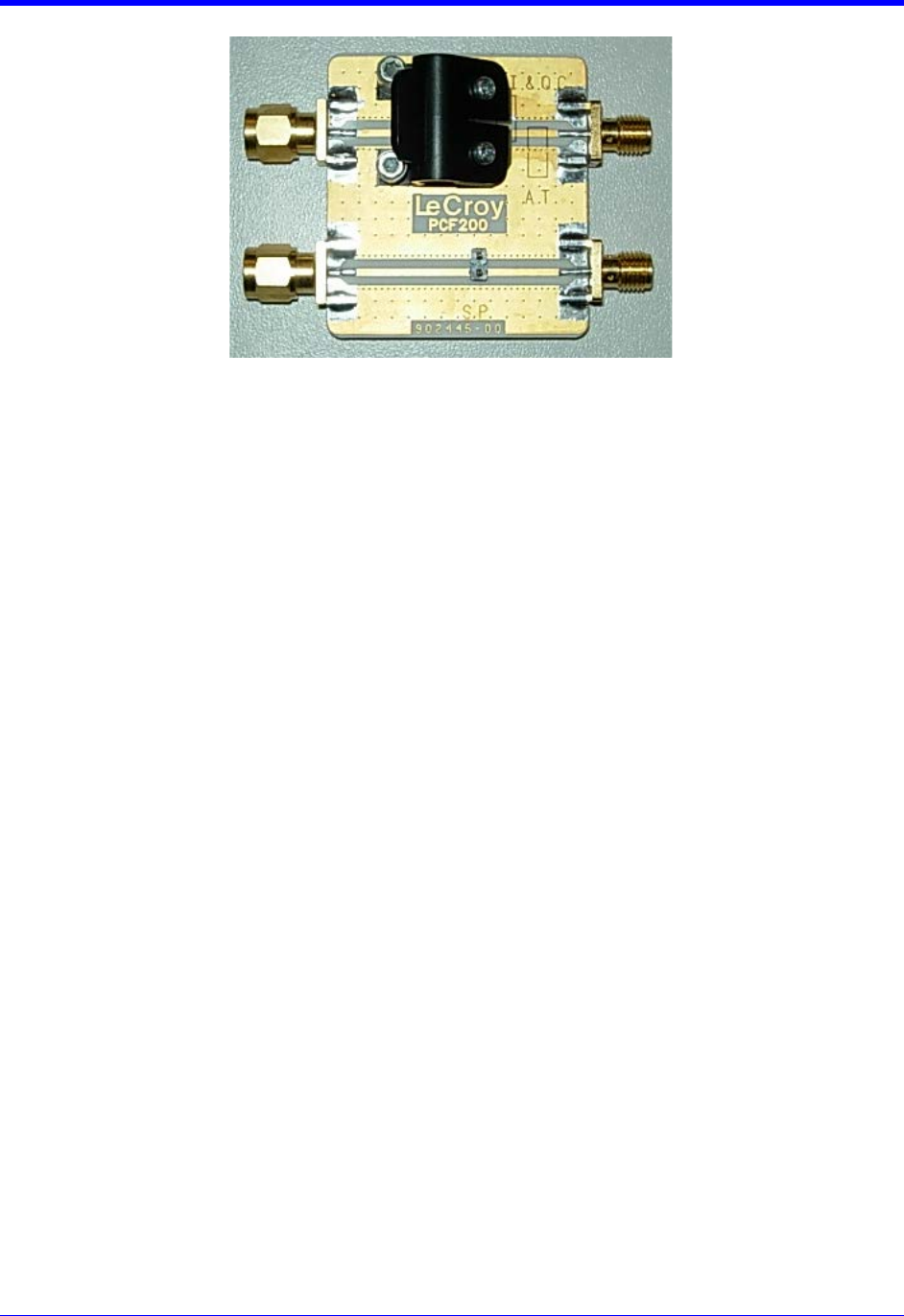
Figure 1. PCF200 Deskew Fixture
A SMA male to BNC male 50-ohm cable is required to perform the calibration.
System assembly is accomplished in the following steps:
1. Connect the BNC end of the 50 ohm cable to the oscilloscope AUX IN input.
2. Connect the SMA end of the 50 ohm cable to the SMA female connector on the PCF200 fixture.
On oscilloscope models with a dedicated Fast Edge SMA output,
3a. Connect the PCF200 SMA male connector to the oscilloscope Fast Edge SMA output.
Skip to the next section.
On oscilloscope models without a dedicated Fast Edge SMA output,
3b. Using an BNC to female SMA adapter, connect the PCF200 SMA male connect to the
oscilloscope AUX OUT output.
4. Under Utilities → U ti lities S et up, select Fast Edge from within the Aux Output tab.
Probe Connection to PCF200
The PCF200 provides multiple probe connectors for various kinds of probes. There are 2 circuits
depending on the type of probes to calibrate:
• The upper circuit is for Solder-In (SI) and Quick-Connect (QC) probes. This circuit can also be
used for AT probes using the designated area to apply the probe tips.
• The lower circuit is for Square-Pin (SP) probes.
Probes are connected electrically in a single-ended arrangement: the positive (+) side of the probe must
be connected to the signal trace, while the negative (-) side is connected to the ground plane. The
positive polarity marking is located on the tip end of the probe in white as a plus sign.