
User Manual


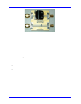
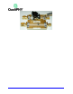
Table Of Contents
- Introduction TO QPHY-DDR3
- Signals measured
- DDR3 MEASUREMENT PREPARation
- Basic Functionality
- Using Qualiphy DDR3
- QualiPHY Compliance Test Platform
- QPHY-DDR3 Test Configurations
- 1) Clock tests DDR3-1333 (1 Probe)
- 2) CKdiff-DQse-DQSdiff 1333 Write Burst (3 Probes)
- 3) CKdiff-DQse-DQSdiff 1333 Read Burst (3 Probes)
- 4) Eye Diagram (3 Probes Debug)
- 5) Eye Diagram with CS Enabled (4 Probes Debug)
- 6) CKDiff-DQse-DQS-ADD/CTRLse (4 Probes Debug)
- 7) CKdiff-DQse-DQSp-DQsn (4 probes test, each DQS signal probed single ended)
- 8) CKp-CKn-DQse-DQSdiff (4 probe test, each CK signal is probed single ended)
- 9) Vref tests
- D1) Demo of All Tests
- QPHY-DDR3 Variables
- QPHY-DDR3 Limit Sets
- QPHY-DDR3 Tests
- Clock Tests
- tCK(avg), Average Clock Period
- tCK(abs), Absolute Clock Period
- tCH(avg), Average High Pulse Width
- tCL(avg), Average Low Pulse Width
- tCH(abs), Absolute High Pulse Width
- tCL(abs), Absolute Low Pulse Width
- tJIT(duty), Half Period Jitter
- tJIT(per), Clock Period Jitter
- tJIT(cc), Cycle to Cycle Period Jitter
- tERR(n per), Cumulative Error
- Eye Diagram
- Electrical Tests
- Timing Tests
- Four Probe tests measurements using ADDR/CTL
- Clock Tests

8 917717 Rev C
DDR3 MEASUREMENT PREPARATION
Before starting any test or data acquisition, the oscilloscope must be warmed for at least 20 minutes.
Calibration is automatic under software control and no manual calibration is required. The procedure
should be run again if the temperature of the oscilloscope changes by more than a few degrees .
Deskewing the Probes
Deskewing the prob es is a mandatory requirement for running QPHY. Given the unknown
conditions posed by individual customer setups, it is required that the customer check the signal
Deskew manually once before giving a thumbs-up on the lane skew and proceedi n g with the
QPHY test. Having a skew on the signal will cause tests to generate erroneous failures or mask
conditions that could be problema tic.
Differential Probe Deskew Procedure using TF-DSQ on non-Zi oscilloscopes
Follow the procedure described in the TF-DSQ Probe Deskew and Calibration Fixture manual. Deskew all
four channels with their respective probe, using external trigger (AUX IN) as reference signal.
You can get more information on TF-DSQ using the oscilloscope Help menu and searching for Probe
Calibrat ion . There is also a section on Des k ew Theor y of Operation.
Differential Probe Deskew Procedure on Zi oscilloscopes using PCF200
Use the PCF200 Characterization Fixture provided as a standard accessory with the WaveLink series
probes. This fixture determines the effect of probe input loading on the circuit under test and the probe
response to the signal being measured, using the AT, ST, Dx10, and Dx20 modules with SI, or SP, or QC
(QC for WL-PLink only) interconnect leads.
PCF200 Fix tur e Overview
Major components of the PCF200 fixture are shown in the following figure:
• SMA male connector Fast Edge input.
• SMA female connector output to AUX IN for 50-ohm termination.
• Clip for connection of Solder-In probes.
• 2-pins header for connection of Square-Pin probes .