
User Manual


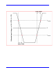

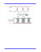
Table Of Contents
- Introduction TO QPHY-DDR3
- Signals measured
- DDR3 MEASUREMENT PREPARation
- Basic Functionality
- Using Qualiphy DDR3
- QualiPHY Compliance Test Platform
- QPHY-DDR3 Test Configurations
- 1) Clock tests DDR3-1333 (1 Probe)
- 2) CKdiff-DQse-DQSdiff 1333 Write Burst (3 Probes)
- 3) CKdiff-DQse-DQSdiff 1333 Read Burst (3 Probes)
- 4) Eye Diagram (3 Probes Debug)
- 5) Eye Diagram with CS Enabled (4 Probes Debug)
- 6) CKDiff-DQse-DQS-ADD/CTRLse (4 Probes Debug)
- 7) CKdiff-DQse-DQSp-DQsn (4 probes test, each DQS signal probed single ended)
- 8) CKp-CKn-DQse-DQSdiff (4 probe test, each CK signal is probed single ended)
- 9) Vref tests
- D1) Demo of All Tests
- QPHY-DDR3 Variables
- QPHY-DDR3 Limit Sets
- QPHY-DDR3 Tests
- Clock Tests
- tCK(avg), Average Clock Period
- tCK(abs), Absolute Clock Period
- tCH(avg), Average High Pulse Width
- tCL(avg), Average Low Pulse Width
- tCH(abs), Absolute High Pulse Width
- tCL(abs), Absolute Low Pulse Width
- tJIT(duty), Half Period Jitter
- tJIT(per), Clock Period Jitter
- tJIT(cc), Cycle to Cycle Period Jitter
- tERR(n per), Cumulative Error
- Eye Diagram
- Electrical Tests
- Timing Tests
- Four Probe tests measurements using ADDR/CTL
- Clock Tests
36 917717 Rev C
tERR(n per), Cumulative Error
tERR is defined as the cumulative error across n multiple consecutive cycles from tCK(avg). tERR is not
subject to production test.
There are 12 different tests:
tERR(2per), tERR (3per), tERR (4per), t ERR (5per), tERR(6per), tERR (7per), tERR (8per), tERR (9per),
tERR (10per), tERR (11per), tERR (12per), tERR (13-50per),
Eye Diagram
Write Bur st (Inputs)
This is an informational only test that creates the eye diagram of all of the write bursts found in the
acquisition. The Eyes are created for both the Data signal and the Strobe signal and shown on the
screen at the same time to allow for debugging of strobe timing.
Read Burst (Outputs)
This is an informational only test that creates the eye diagram of all read bursts found in the acquisition.
The Eyes are created for both the Data signal and the Strobe signal and shown on the screen at the same
time to allowing for strobe timing debugging.
Electrical Tests
Write Bursts (Inputs)
Slew (Input Slewrate)
This test applies to all input signals.
SlewR and SlewF
Apply to all input signals.
The input signal minimum slew rate is to be maintained over the range from VREF to VIH(ac) min for
rising edges (SlewR) and the range from VREF to VIL(ac) max for falling edges (SlewF) of single-ended
signal. This test is informational only.