
User Manual


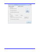


Table Of Contents
- Introduction TO QPHY-DDR3
- Signals measured
- DDR3 MEASUREMENT PREPARation
- Basic Functionality
- Using Qualiphy DDR3
- QualiPHY Compliance Test Platform
- QPHY-DDR3 Test Configurations
- 1) Clock tests DDR3-1333 (1 Probe)
- 2) CKdiff-DQse-DQSdiff 1333 Write Burst (3 Probes)
- 3) CKdiff-DQse-DQSdiff 1333 Read Burst (3 Probes)
- 4) Eye Diagram (3 Probes Debug)
- 5) Eye Diagram with CS Enabled (4 Probes Debug)
- 6) CKDiff-DQse-DQS-ADD/CTRLse (4 Probes Debug)
- 7) CKdiff-DQse-DQSp-DQsn (4 probes test, each DQS signal probed single ended)
- 8) CKp-CKn-DQse-DQSdiff (4 probe test, each CK signal is probed single ended)
- 9) Vref tests
- D1) Demo of All Tests
- QPHY-DDR3 Variables
- QPHY-DDR3 Limit Sets
- QPHY-DDR3 Tests
- Clock Tests
- tCK(avg), Average Clock Period
- tCK(abs), Absolute Clock Period
- tCH(avg), Average High Pulse Width
- tCL(avg), Average Low Pulse Width
- tCH(abs), Absolute High Pulse Width
- tCL(abs), Absolute Low Pulse Width
- tJIT(duty), Half Period Jitter
- tJIT(per), Clock Period Jitter
- tJIT(cc), Cycle to Cycle Period Jitter
- tERR(n per), Cumulative Error
- Eye Diagram
- Electrical Tests
- Timing Tests
- Four Probe tests measurements using ADDR/CTL
- Clock Tests

QPHY-DDR3 Software Opti on
917717 Rev C 11
The probe calibration menu can be accessed from the Vertical drop-down menu or from the channel
dialog:
Figure 3. Accessing the probe c alibration menu
Figure 4. Basic Probes Calibration menu
The information in the probe calibration menu is organized such that each row represents the information
for a given channel, and each column represents the calibration information or control for that channel.
Pr o be Calibrati o n P r o c e dure
Depending on the compliance test that is to be performed, probes must connect with certain channels.
This is especially important when probes of different models are used simultaneously. The connection
setup for a particular test can be found in the pop-up dialog box after pressing the start button in Qualiphy.
Should probes be calibrated on the wrong channel, this procedure must be rerun.
Complete the following to properly deskew each probe.
1. Connect probes to their respective channel.
2. Select FastEdge for Cal Source.
3. Select EXT for for Cal Skew Ref.
The following is to be performed separately with each probe.