FLEXRAY TRIGGER, DECODE, AND PHYSICAL LAYER TEST Operator’s Manual MARCH, 2008
LeCroy Corporation 700 Chestnut Ridge Road Chestnut Ridge, NY 10977–6499 Tel: (845) 578 6020, Fax: (845) 578-5985 Internet: www.lecroy.com © 2008 by LeCroy Corporation. All rights reserved. LeCroy, ActiveDSO, JitterTrack, WavePro, WaveMaster, WaveSurfer, WaveLink, WaveExpert, and Waverunner are registered trademarks of LeCroy Corporation. Other product or brand names are trademarks or requested trademarks of their respective holders. Information in this publication supersedes all earlier versions.
OPERATOR’S MANUAL TABLE OF CONTENTS INTRODUCTION ........................................................................................................................................4 Overview .................................................................................................................................................................... 4 The TDP Series Software .............................................................................................................................
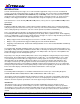
INTRODUCTION Several communication protocol types are used in automotive applications. They are used to send data from sensors to electronic control units (ECUs) or from one ECU to another. These protocol types include Controller Area Network (CAN), Local Interconnect Network (LIN) and FlexRay. LIN is a low-cost master/slave system designed for low-cost implementation in vehicles, typically in what is commonly referred to as “body electronics.
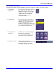
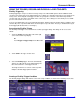
OPERATOR’S MANUAL The TDP Series Software The TDP option adds the following capability to the LeCroy oscilloscope software user interface dialogs: 1. Serial Trigger Selection If this is the first serial trigger option you have installed on your scope, an additional icon appears in your trigger dialog box. It allows a serial trigger condition to be set from within the oscilloscope using an easy-tounderstand interface. 2.
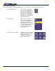
The TD Series Software The TD option adds the following capability to the LeCroy oscilloscope software user interface dialogs: 6 1. Serial Trigger Selection If this is the first serial trigger option you have installed on your scope, an additional icon appears in your trigger dialog box. It allows a serial trigger condition to be set from within the oscilloscope using an easyto-understand interface. 2.
OPERATOR’S MANUAL The D Series Software The D option adds the following capability to the LeCroy oscilloscope software user interface dialogs: 1. Serial Decode If this is the first serial decode option you have installed on your scope, an additional set of Serial Decode and Decode Setup dialog boxes are provided for setup of protocol format (as necessary) and decoding. 2. Decode Protocol Selections FlexRay is one of several signal types that can be decoded by the oscilloscope.
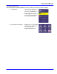
TECHNICAL OVERVIEW OF D, TD, AND TDP OPTIONS LeCroy’s offering of FlexRay trigger, decode and physical layer test options utilize advanced trigger circuitry and advanced software algorithms to provide powerful capability for serial data triggering and decoding. FlexRay Trigger FlexRay TDP and TD options contain advanced serial data triggering.
OPERATOR’S MANUAL USING THE TRIGGER, DECODE AND PHYSICAL LAYER TOOLSETS FlexRay Triggering FlexRay triggering is easily accessible in a variety of ways. The TD and TDP options add an additional Serial selection to the Trigger Type in the Trigger dialog. These dialogs are shared by all the low-speed serial protocols LeCroy offers. This is why all serial trigger selections are grouped in a common section with nearly identical selection and setup procedures (if installed on the oscilloscope).
The Source Setup information must be defined. The datasheet for your part should contain the information you need to properly setup the FlexRay Trigger. Selection of Trigger Type results in dynamic changes to the FlexRay Trigger dialog. To select a value for any of the conditions, touch the existing value (using your finger, or use a mouse pointer) to open the pop-up dialog box with a list of choices, and select one of the choices.
OPERATOR’S MANUAL Cycle Count – The Cycle Count is combined with the Frame ID to enable powerful FlexRay triggering. The Cycle Count is a decimal value between 0 and 63 and correlates to the FlexRay Cycle Count numbering system. The default Value is Cycle Count 0. If the cycle count is not intended to be part of the Frame triggering, the condition can be set differently to accommodate such scenarios. Possible conditions are <=, <, =, >, >=, not =, In Range of, or Out of Range. The default setting is Equal.
Error Trigger Setup This set of checkboxes are shown if Error is selected as the trigger type. The errors are broken in to 2 categories, Protocol Errors and CRC Errors. Protocol Errors: • • • Frame Start Sequence (FSS) Byte Start Sequence (BSS) Frame End Sequence (FES) CRC Errors: • • • • • • Header CRC Payload CRC The correct channel must be selected when triggering on CRC errors Check or uncheck each one, as desired, to include or not include that specific type of error in the trigger.
OPERATOR’S MANUAL 3. Touch a Channel, Memory, or Math trace to open a pop-up dialog that displays a shortcut to the Decode Setup dialog box Serial Decode (Summary) Dialog Box The Serial Decode dialog box is a summary page of which decoders are ON, and how they are set up. In addition, there are shortcuts to Decode Setup and Search. There are four independent decoders.
Data Selection – This pop-up dialog allows you select the channel or other source for decoding. Decode Setup Shortcut Button – This provides quick access to the second tab (Decode Setup) where there are quick buttons for Search, and Table (Configure Table and Export Table). If you have already defined the trigger, then the trigger setup settings copy over into the decode setup. Search – Push this button to open a Zoom (Zx trace) that has, as its source, the corresponding Channel (Cx trace).
OPERATOR’S MANUAL View Table Checkbox – Checking this box turns the Table ON. Unchecking it turns the Table OFF. Note: If the View Decode checkbox is not checked (i.e. decode is not ON), then the View Table checkbox is grayed out. The Table cannot display unless decode is occurring. When the Table is displayed, it appears similar to that shown to the right.
Decode Setup Detail The FlexRay Decode Setup Right-Hand Dialogs (which are contained in the Decode Setup dialog box when FlexRay is selected as the Protocol to decode), with detail on the setup conditions, is shown in the images that follow: BitRate – Adjust the bit rate value here to match the bit rate on the bus you are connected to. This bit rate selection is dynamically linked to the decoding bit rate (they are always the same value). Use the arrows to move through standard bit rates (2.5, 5.0 or 10.
OPERATOR’S MANUAL Protocol Results Table The protocol results table provides a quick and easy way to understand all of your FlexRay data as decoded by the oscilloscope, even when messages are too compacted to allow annotation on the display. In addition, the table provides a quick and easy method to look at decode results, and quickly zoom to a specific message. When displayed, the protocol results table appears under the waveform grid.
Searching for Messages There are several ways to search for specific messages. 1. Touch the decoded waveform to open a pop-up dialog OR 2. Touch the Search button in the Serial Decode Summary dialog box or the Decode Setup dialog box OR 3. From the File Menu, go to Math, and choose Zoom Setup to turn a Zoom ON, define its source, and search directly. Any of the previous three steps take you to a Zoom dialog box with Search functionality in its own dialog box section at the right.
OPERATOR’S MANUAL Eye Diagram and Mask Test Setup Detail The Left Hand side of the FlexRay Physical Layer tab has all the settings for Eye Diagram Mask testing as seen below. Input Signal Setup Source – The pop-up dialog is used to select the channel, math or memory waveform to use for the eye diagram creation Bitrate – The eye diagram can be created from FlexRay waveforms with bitrates of 2.5 Mb/s, 5 Mb/s and 10 Mb/s as defined in the FlexRay specification.
Mask Test Display The FlexRay TDP option allows you to verify signal integrity of the communication channel and corresponding protocol data simultaneously as seen below. Points where the FlexRay signal intersects the mask are indicated with red failure marks. 10 Mb/s FlexRay signal being tested on a TP1 mask Physical Layer Measurement Parameters The FlexRay TDP option provides four measurement parameters that are defined in the FlexRay physical layer specification.
OPERATOR’S MANUAL Physical Layer Measurement Setup Detail The Right Hand side of the FlexRay Physical Layer tab has the settings for physical layer measurements. Measurement Parameter Setup Source – Select the emitting and receiving nodes on the FlexRay channel where Propagation Delay, Asymmetric Delay and Truncation are being measured. Jitter is measured on a single channel. Measurements – Select one of the 4 FlexRay physical layer measurements. As the boxes are checked the measurement values are shown.
Just like other measurement parameters statistical information can be displayed and the results can be shown visually in a histicon directly below the measured values. FlexRay measurements can be selected as the source for track, trend or histogram functions. More detail on these functions is described in a different section of this manual.
OPERATOR’S MANUAL Using Cursors Use horizontal cursors to mark locations on the waveform where the time measurement should be done, then read the cursor values to establish the measurement. As necessary, adjust the timebase or create zooms of the decoded trace(s) so as to be able to view the signal with enough detail. This is a good method for single-shot / single measurements.
Maximum – Highest value in the input waveform. Mean – Average of all data values. Minimum – Lowest value in the input waveform. Overshoot Negative – Overshoot following a falling edge. Overshoot Positive – Overshoot following a rising edge. Peak to Peak – Difference between the Maximum and Minimum data values. Rise (10-90), Rise (20-80), Rise@Level –Transition time on the rising edge. Three selections are available for the user to determine at which vertical level the measurement is made.
OPERATOR’S MANUAL Pass/Fail Analysis with Measurement Parameters Pass/Fail analysis using measurement parameters is quite simple to set up and quite powerful. For instance, you can define a timing measurement, define the limits for the timing measurement, and then run the oscilloscope in a Normal trigger mode, capturing thousands of measurement events. Then, for example, Pass/Fail can be used to save the Waveform in the event of a Fail, or send an email in the event of a fail.
Trigger Repeatedly, Save Data to a Hard Drive You may wish to set up your oscilloscope to capture a short or long memory acquisition for a certain trigger condition, then save data to a hard drive or memory stick whenever the trigger condition is met. This can be easily done in most LeCroy oscilloscopes. However, you must realize that there is significant trigger “dead time” when using this method. To minimize dead time, use the method described under Trigger Repeatedly, Store all Triggers (Sequence Mode).
OPERATOR’S MANUAL 2. In the Sampling Mode area, select Sequence Mode. Touch the Sequence tab (now showing next to the Timebase tab). 3. On the Sequence tab, select the Display Mode. Select the Number of Segments Displayed at one time. 4. If you have acquired more segments than you can display at one time, you can choose which segment at which to start the display. 5. As described previously in this manual, set up the Serial Trigger to capture the event you desire.
6. Display an individual segment separately from the main channel display by selecting Math Æ Math Setup from the menu bar. Now, choose a math trace to define as a Segment (here we’re defining F1 as a Segment of C2). Use the channel the serial data was acquired on as a source (in this case Channel 2). Check the TRACE ON checkbox to display the trace. Select a segment to view by touching the Select tab and use either the pop-up keypad or the front panel adjust knob. 7.
OPERATOR’S MANUAL 8. Conserve display space, by turning off the Channel and selecting only the segment you wish to view. 9. View the timestamps for each segment by selecting Vertical Æ Channels Status on the menu bar. On the Show Status portion of the dialog, select Time (shown right). A display of timestamp information for each segment in the sequence acquisition is then shown (as follows). 10. Ten timestamps fit on the display at a time.
APPENDIX A – FLEXRAYBUS TDP AND TD SPECIFICATIONS FlexRaybus TDP Definition Protocol Setup Select BitRate (2.5, 5 or 10 Mb/s) Select FlexRay Channel A or Channel B Decode Capability Format All decoding is hexadecimal except for Cycle Count which is decoded using a decimal format Two threshold definitions required. Default is to Percent amplitude. Decode Setup Select BitRate. Select FlexRay Chanel A or Channel B Decode Input Any analog Channel, Memory or Math trace.
OPERATOR’S MANUAL Trigger Capability Format Hexadecimal or Binary for Frame ID Decimal for Cycle Count Trigger on TSS (Start), Frame ID, Cycle Count, Symbols and Errors Symbols: Channel Idle Delimiter (CID) Symbol, Collision Avoidance Symbol (CAS), Media Access Test Symbol (MTS), Wakeup Pattern (WUP) Trigger Setup Errors: Frame Start Sequence (FSS) Error – triggers when the logic high time between the TSS and the first byte is too long Byte Start Sequence (BSS) Error – triggers anytime the BSS pattern i
FlexRaybus TD Definition Protocol Setup 32 Includes all Decode, Trigger and Search functionality described in FlexRaybus TDP, no Physical Layer Test included FlexRay-TDP-OM-E Rev A