
Users Manual Instruction Manual


5
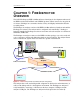
CATC FIREINSPECTOR 2.01 CHAPTER 1
User’s Manual FireInspector Overview
• Power on/off switch
• USB type “B” host computer connector
• Data In/Out DB-37 (37-pin) external interface connector
Data In/Out Connector
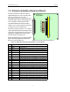
The 37-pin Data In/Out connector, shown in
Figure 1-5, provides a convenient method for
connecting the External Interface Breakout
Board. See page 6 for details regarding the
External Interface Breakout Board. The Data
In/Out connector is located on the back of the
FireInspector analyzer box as shown in
Figure 1-4.
Table 1-1 lists the pin-out and signal descriptions for the Data In/Out connector.
Trigger/signal inputs (Ix) function under control of the FireInspector program and may be
assigned as active-low or active-high by settings in the Recording Options. Signal outputs
(Ox) function under the control of the FireInspector program and are used to link any
triggered events to an external signal.
Table 1-1: Data In/Out Connector – Pin-Out
Pin Signal Description Pin Signal Description
1 5V, 500mA DC source 20 Ground
2 - Trigger Output (active low) 21 Ground
3 Not connected 22 Ground
4 I 0 – Trigger/signal input 23 Ground
5 I 1 – Trigger/signal input 24 Ground
6 I 2 – Trigger/signal input 25 Ground
7 I 3 – Trigger/signal input 26 Ground
8 I 4 – Trigger/signal input 27 Ground
9 I 5 – Trigger/signal input 28 Ground
10 I 6 – Trigger/signal input 29 Ground
11 I 7 – Trigger/signal input 30 Ground
12 O 0 – Signal output 31 Ground
13 O 1 – Signal output 32 Ground
14 O 2 – Signal output 33 Ground
15 O 3 – Signal output 34 Ground
16 O 4 – Signal output 35 Ground
17 O 5 – Signal output 36 Ground
18 O 6 – Signal output 37 Ground
19 O 7 – Signal output
1
20
19
37
Figure 1-5: Data In/Out Connector