
Users Manual Instruction Manual


4
CATC FIREINSPECTOR 2.01 CHAPTER 1
User’s Manual FireInspector Overview
• Push-button Trigger switch is used to manually force a trigger event during a recording
session.
•Red PWR (power) indicator LED. The LED illuminates when the unit is powered on.
IEEE 1394 6-Pin Port Connectors
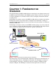
The 1394 bus is an unsupervised connection of nodes in a tree structure. The only restriction
is that there can be no loops. The FireInspector analyzer box is equipped with three identical
and interchangeable IEEE 1394 ports: Port 1, Port 2, and Port 3. The analyzer is a node with
three connectors. Using the three connectors as necessary, the analyzer can be connected to
one node, inserted between any two or three nodes of a tree, or as a leaf. Connect the
analyzer box to the 1394 bus network that is being tested. Figure 1-3 provides three
examples of analyzer configurations.
The Trigger Push-Button
The push-button Trigger switch provides the means to manually force a trigger event during
a recording session. The session finishes when a specified post-trigger amount of bus data
is recorded.
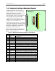
1.3.2 Back Panel Description
The rear panel, shown in Figure 1-4, includes, from left to right, the following items:
• 120 Volt AC connector module
• Power socket
• Enclosed fuse
Figure 1-3: Analyzer configuration examples
Figure 1-4: FireInspector back panel
PWR
Tr igger
TriggeredRecording
Po rt 1 Po rt 2 Po rt 3
CATC IEEE 1394 Bus Analyzer
PWR
Tr igger
Trig geredRecording
Po rt 1 Po rt 2 Po rt 3
CATC IEEE 1394 Bus Analyzer
PWR
Tr igg er
Tr ig g eredRecording
Port 1 Port 2 Port 3
CATC IEEE 1394 Bus Analyzer
Node
Leaf
Leaf
Leaf Leaf Leaf
Root
Leaf
Node
Leaf
RootRoot
1
20
19
37
USB
Data In/Out