
Users Manual Instruction Manual


3
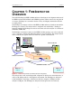
CATC FIREINSPECTOR 2.01 CHAPTER 1
User’s Manual FireInspector Overview
Please refer to the IEEE Std 1394 for details on the protocol. The IEEE 1394 specification
is available from the Institute of Electrical and Electronic Engineers (IEEE); it can be
ordered by sending e-mail to customer.service@ieee.org. Other information regarding the
IEEE 1394 application is available from the 1394 Trade Association at:
1.2 The FireInspector Analyzer System Components
The FireInspector analyzer package includes the following items:
• One FireInspector analyzer unit with AC power cord
• One External Interface Breakout Board with a 37-pin ribbon cable
• One USB cable
• Two IEEE 1394 cables
• One 6/6 pin
• One 6/4 pin
• FireInspector software program installation diskette(s)
• Product documentation including on-line Help
1.3 The FireInspector Analyzer Unit
The FireInspector analyzer has several user-accessible controls on its front and back panels.
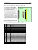
1.3.1 Front Panel Description
The front panel, shown in Figure 1-2, includes, from left to right, the following items:
• Three IEEE 1394 6-pin connectors labeled Port 1, Port 2 and Port 3.
•Green Recording LED illuminates when the unit is recording.
• Yellow Triggered LED lights up when a trigger event occurs during a recording session.
This LED also lights up during power-on testing and will blink when the hardware is
faulty.
1394 Trade Association
1111 South Main Street, Suite 100
Grapevine, Texas 76051
Tel: +1/817.410.5750
Fax: +1/817.410.5752
Web: http://www.1394ta.org/
Figure 1-2: FireInspector front panel
FireInspector
™
Port 2 Port 3
Recording Triggered
Trigger
PWR
Port 1