
Users Manual Owner's manual

23
BTTracer Protocol Analyzer User’s ManualCATC SW Version 2.20
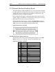
Note (*) Pins 4 and 17 have the same function: they allow external
signals to be used to cause triggering or recording. Pins 3 and 16
are used to transmit output signals. Pins 6, 7, 8, 9, 18, 19, 21, and
22 (data pins) are used to define data patterns for external input
signals. See External Input Signals in Chapter 6.
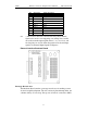
External Interface Breakout Board
Prototype Rework Area
The Breakout Board contains a prototype rework area for making custom
circuits for rapid development. The area consists of plated-through holes, 20
columns wide by 27 rows long. The top row of holes is connected to GND
16 TRG OUT Trigger Out
17 TRG IN 0 Trigger In 0
18 DATA 7 Data 7
19 DATA 5 Data 5
20 GND Ground
21 DATA 2 Data 2
22 DATA 0 Data 0
23 GND Ground
24 RSV Reserved
25 RSV Reserved
Pin Signal Name Signal Description