
Users Manual Owner's manual

22
BTTracer Protocol Analyzer User’s ManualCATC SW Version 2.20
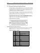
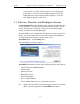
2.9 External Interface Breakout Board
The External Interface Breakout Board is an accessory that allows standard,
LV TTL signals to be channeled into the analyzer for triggering or out of the
analyzer for use by an oscilloscope, logic analyzer or other device. Six
ground pins and one 5-volt pin are provided.
Drive strength for all outputs is about 30mA high (@2V) and 60 mA low
(@0.5V). Inputs can handle 0 to 5.5V. Inputs above 2V are detected as logic
high; inputs below 0.8V are detected as logic low.
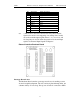
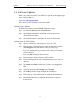
The Breakout Board connects via a cable to the Data In/Out connector
located on the rear of the analyzer unit. Each signaling pin is isolated by a
100Ω series resistor and a buffer inside the Analyzer unit.
Data In/Out Connector (on cable)
Pin-Outs for the Data In/Out Connector
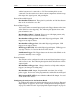
The following table lists the pin-out and signal descriptions for the Data
In/Out connector on a cable that connects to the Breakout board.
Data In/Out Connector – Pin-Out
Pin Signal Name Signal Description
1RSV Reserved
2 GND Ground
3 GP OUT General Purpose Output
4 TRG IN 1 Trigger In 1
5 GND Ground
6 DATA 6 Data 6
7 DATA 4 Data 4
8 DATA 3 Data 3
9 DATA 1 Data 1
10 GND Ground
11 RSV Reserved
12 RSV Reserved
13 +5V +5 Volts, 250 mA DC Source
14 RSV Reserved
15 GND Ground