
Instructions


AP033 Active Differential Probe
46
7. Insert and tighten the two screws which secure the end panel to the ProBus interface
housing. Avoid over tightening the screws as the cover may warp.
8. Replace the four push button caps, pressing each fully to seat the cap on the button
shaft.
J. Attenuator Matching and Final Check
1. Repeat the Performance Verification procedure to ensure compliance with the
warranted specifications.
2. Perform the Attenuator Matching Procedure listed on page 21. Apply calibration
seals in accordance with your quality procedures.
This concludes the Adjustment Procedure. Repeat the Performance Verification
procedure to complete the calibration of the AP033.
Reference Information
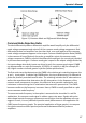
Differential Mode and Common Mode
Differential probes amplify the voltage difference that appears between the + and –
inputs. This voltage is referred to as the Differential Mode or Normal Mode voltage. The
voltage component that is referenced to earth ground, and is identical on both inputs, is
rejected by the amplifier. This voltage is referred to as the Common Mode voltage,
because it is common to both inputs. The common mode voltage can be expressed as:
Differential Mode Range and Common Mode Range
The Differential Mode Range is the maximum signal that can be applied between the
+
and
–
inputs without overloading the probe amplifier, resulting in “clipping” or distortion
of the waveform measured by the oscilloscope.
The Common Mode Range is the maximum voltage with respect to earth ground that can
be applied to either input. Exceeding the common mode range can result in unpredictable
results. Because the Common Mode signal is normally rejected and is not displayed on
the oscilloscope, you need to be careful to avoid accidentally exceeding the common
mode range.