
Instructions


AP033 Active Differential Probe
44
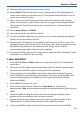
9. Adjust GAIN (R322C) so that the DMM reading is within ±1 mV (0.5%) of the reading
recorded in step F-6. (See Figure 11.)
10. Set AP033 probe Gain to X10, and probe Attenuation to /10.
11. Verify that the DMM reads within 1 mV of the reading recorded in step F-6. If the
error exceeds 1 mV, readjust GAIN (R322C) for an error amplitude of ½ of the value
before making the readjustment. Compromise as necessary to center the error
voltage in both gain/attenuation combinations, making sure that the final errors are
less than 1 mV.
12. Disconnect the Function Generator, DMM, calibration fixture, and precision 50 Ω
terminator.
G. Adjust Final Attenuator Compensation (C17A)
NOTE: The calibrator signal from a Teledyne LeCroy oscilloscope is the recommended
signal source for this adjustment. If another oscilloscope is being used for this procedure,
make sure that the square wave source has adequate flatness (minimum overshoot and
undershoot.)
1. Press the UTILITIES button, then select the CAL BNC Setup menu. Set the Mode to
CAL signal, the Shape to Square, the Amplitude to 1 V into 1 M Ω, and the Frequency
to 1 kHz.
2. Set AP033 probe Attenuation to /10 and probe Gain to X10.
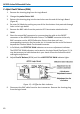
3. Reconnect the free end of the ProBus Extender BNC cable to the oscilloscope end of
the extender located on Channel 1.
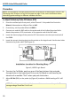
4. Connect a BNC cable from the CAL output BNC connector to the Differential Drive 50
Ohm Termination connector on the AP033 Calibration Fixture.
5. Carefully attach the Differential Drive 50 Ohm Termination portion of the AP033
Calibration Fixture to the probe tip. Press the probe into the fixture to fully engage
the pins.
6. Set the oscilloscope’s Channel 1 vertical scale factor to 50 mV/div, and the horizontal
scale to 1 μs/div. Set the trigger source to Channel 1, and Slope to Positive. Adjust
the oscilloscope trigger level as necessary for a stable display.
7. Adjust the trace offset until the top portion of the waveform is centered.
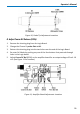
8. Adjust Attenuator Comp (C17A) for a flattop waveform. See Figure 10 for adjustment
location.