
Instructions


Operator’s Manual
43
15. Note the amplitude of the trace from center screen.
16. Adjust Offset (R330) to position the trace to approximately ½ the amplitude from
center screen noted in the previous step. This amplitude should be within 10 mV of
center screen. Note this value.
17. Again, remove the dual banana plug adapter from the output of the DC voltage
source and reconnect it, with the pins reversed. The plug corresponding to the BNC
shield (marked “Ground”) should now be connected to the – (Common) Output
connector.
18. Set the probe offset to –0.4000 V.
19. Allow 10 seconds for the AP033 to stabilize.
20. The trace should be offset from the center line by the same amplitude but opposite
polarity of the value noted in step 16.
21. Repeat steps E-12 through E-20 as necessary until the errors at +0.4 V and at –0.4 V
are approximately equal and within 10 mV of center scale. Reverse the polarity of the
dual banana plug adapter at the output of the DC voltage source, and the
corresponding probe offset value with each repetition.
22. Disconnect the cable from the DC Voltage Source. Keep the AP033 Calibration Fixture
connected to the AP033 for the next step.
F. Adjust GAIN (R322C)
1. Set the AP033 offset to 0.000 V. Make sure the probe is still set to /1 Attenuation
and X1 Gain.
2. Disconnect the BNC cable from the oscilloscope end of the ProBus extender cable.
Reconnect the end of the cable to the precision 50 Ω termination.
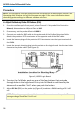
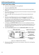
3. Connect one end of a second BNC cable to the output of the Function Generator.
Attach the BNC to dual male banana plug adapter to the free end of the BNC cable.
Insert the banana plugs of the adapter into the input terminals of the Digital
Multimeter (DMM).
4. Set the DMM to measure AC Volts.
5. Set the mode of the Function Generator to Sine Wave, the frequency to
approximately 1 kHz, and the output amplitude to read approximately 200 mV on the
DMM.
6. Record the DMM reading. Be careful not to alter the output amplitude of the
generator after the measured value has been recorded.
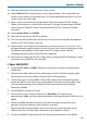
7. Remove the banana plug adapter and connect the free end of the cable to the
Differential Drive no Termination connector on the calibration fixture.
8. Connect the AP033 Output cable with 50 Ω precision termination to the DMM.