
Instructions


AP033 Active Differential Probe
42
Continuous, with 1:15 weighting, of Channel 3. Turn off the trace 3 display. Use the
Math Zoom and Position controls as necessary to view the waveform.
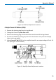
12. Adjust ÷ CMRR (R7) for minimum amplitude. (See Figure 10 for location.)
13. Remove the BNC cable from the output of the Function Generator and the calibration
fixture. Leave the BNC cable from the SYNC output to the oscilloscope external
trigger input in place. Remove the BNC cable and 50Ω terminator from Channel 3.
E. Adjust OFFSET (R330)
1. Set AP033 probe Attenuation to /1 and Gain to X1. Set the Channel 1 scale factor to
2 mV/div, and the acquisition mode to Auto. Set the BWL to 20 or 25 MHz . Adjust
the OFFSET to 0.0 mV.
2. Carefully move the AP033 probe tip from the Common Mode Drive No Termination
position of the AP033 Calibration Fixture to the Differential Drive No Termination
position. Press the probe into the fixture to fully engage the pins.
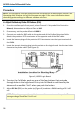
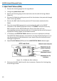
3. Attach the female BNC to dual male banana plug adapters to each end of the BNC
cable. Plug one end into the output of the DC voltage source, making sure that the
plug corresponding to the BNC shield (marked “Ground”) is connected to the voltage
source – output (or common for dual supplies) connector, and the other pin on the +
output connector.
4. Connect the other end of the cable to the DMM input, making sure that the plug
corresponding to the BNC shield (marked “Ground”) is connected to the LO or COM
input.
5. Set the DC Voltage Source to read as close as possible to +0.4000 V on the DMM.
6. AutoZero the AP033.
7. Disconnect the BNC cable from the female BNC-to-dual male banana plug adapter on
the DMM.
8. Reconnect the BNC cable from the DC Voltage Source to the Differential Drive No
Termination connector on the AP033 Calibration Fixture.
9. Set the probe offset to –0.4000 V.
10. Allow 10 seconds for the AP033 to stabilize.
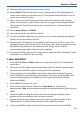
11. Adjust Offset (R330) to bring the trace back to exactly center screen. (See Figure 11.)
12. Remove the dual banana plug adapter from the output of the DC voltage source and
reconnect it, with the pins reversed. (The plug corresponding to the BNC shield
(marked “Ground”) should now be connected to the + Output connector.)
13. Set the probe offset to +0.4000 V.
14. Allow 10 seconds for the AP033 to stabilize.