
Instructions


Operator’s Manual
41
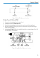
D. Adjust ÷10 Attenuator CMRR (R7)
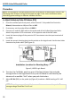
1. Keep the BNC cable attached to the probe end of the ProBus extension cable. Attach
a 50Ω BNC Through Terminator on the other end of the BNC cable. Attach the male
end of the 50Ω terminator to Channel 3 on the oscilloscope. The oscilloscope end of
the ProBus extension cable should remain connected to Channel 1 of the oscilloscope
although there is no signal cable attached.
2. Set AP033 probe Attenuation to /10 and Gain to X10.
3. Connect a BNC cable from the output of the Function Generator to the Channel 2
input of the oscilloscope.
4. Connect a second BNC cable from the Function Generator SYNC OUT to the external
trigger input of the oscilloscope.
5. Set the Function Generator waveform to Sine and the frequency to 70 Hz.
6. Set the oscilloscope as follows:
Display: Channel 2
Channel 1 VOLTS/DIV: 2 mV/div
Channel 2 VOLTS/DIV:
5 V/div
Channel 3 VOLTS/DIV: 2 mV/div
Channel 2 Coupling: DC1MΩ
Channel 3 Coupling: AC 1MÙ
Trigger on: EXT10
cplg EXT10:
DC
TIME/DIV: 10 ms/div
Acquisition Mode: NORMAL
7. Adjust the trigger level for a stable display.
8. Set the Function Generator output voltage to 20 Vp-p as displayed on the
oscilloscope.
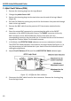
9. Disconnect the output cable of the function generator from the Channel 2 input of
the oscilloscope and reconnect it to the Common Mode Drive No Termination
connector of the AP033 Calibration Fixture.
10. Carefully align the four pins that correspond to the Common Mode Drive No
Termination portion of the AP033 Calibration Fixture with the input receptacles in
the AP033 probe head. Press the probe into the fixture to fully engage the pins.
11. Set the oscilloscope to display Channel 3. The waveform is the common mode signal.
Turn the offset as necessary to keep the trace on screen. Turn on Math Channel A.
Press MATH SETUP, then REDEFINE A. Set the A Math type to Average, Avg Type to