
Instructions


Operator’s Manual
37
Preliminary Procedure
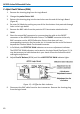
1. Using pliers, carefully remove each of the push buttons from the ProBus interface
housing by gently pulling them away from the housing.
2. Remove the two screws that secure the plastic cover on the cable end of the ProBus
interface housing. Gently pull on the probe cable to slide the circuit board assembly
from the metal housing.
3. Remove the two, M2X6 flat socket head cap screws from the small cover on the back
of the probe tip. Remove the cover along with the small cover on the opposite side of
the probe. Hold the shielded portion of the probe head in one hand and gently slide
the larger cover off by pulling it away from the probe tip end.
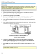
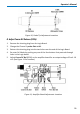
4. Connect the AP033 probe output to the female end of the ProBus Extension Cable.
Be careful to align the ProBus pins with the corresponding connector correctly.
Connect the male end of the ProBus Extension Cable to Channel 1 of the oscilloscope.
NOTE: The Logic board is connected to the Amplifier board by four small 8-pin
connectors. There are no additional mechanical fasteners holding the two boards
together. Be sure that the connectors between the boards are firmly engaged before
applying power to the probe. Operating the probe without the logic board will not
damage it. However, to ensure reliable operation, the logic board should only be
mated with the Amplifier board with the power removed, and the ProBus connector
disengaged.
5. Apply power to the oscilloscope and to the other test instrumentation. Allow at least
30 minute’s warm-up time for the AP033 probe and test equipment before
continuing the calibration procedure.
NOTE: The probe tip cover also serves to thermally stabilize the input circuitry. The
differential input stage of the probe utilizes discrete transistors that need to maintain
an approximate match of junction temperatures for correct DC balance. With the
covers removed, this circuitry is susceptible to drift caused by air currents flowing
over the components. Remove or redirect any fans that may be blowing air currents
over the probe tip during adjustment.