
Instructions


AP033 Active Differential Probe
30
C. Check Low Frequency CMRR
NOTE: The attenuation of the AP033 Active Differential Probe below 10 MHz is so
insignificant that the Differential Mode Gain can be assumed to be unity (1.0). Because
greater amplitudes are required to measure the higher CMRR specifications at low
frequencies, the Function Generator will be used in place of the leveled sine wave
generator for the low frequency CMRR test.
1. Carefully move the AP033 probe head from the Common Mode Drive 50 Ohm
Termination connector of the AP033 Calibration Fixture to the Common Mode Drive
No Termination connector. Make that sure the probe is fully engaged in the fixture.
2. Set the oscilloscope to display Channel 2, the Channel 2 input coupling to DC1 MΩ,
the Channel 2 vertical scale to 1 Volt/div, the horizontal scale to 1 ms/div, and the
trigger source to Channel 2. Set BW limiting on channels 1 and 2 to 25 MHz (BW may
be limited to 20 MHz on X-Stream oscilloscopes).
3. Set the AP033 Coupling to DC 1MΩ, Attenuation to /1, and Gain to X1.
4. Attach a BNC cable from the output of the Function Generator to the BNC T adapter.
Attach the BNC T adapter on the output connector of the Function Generator.
Connect a BNC cable from one end of the BNC T adapter to channel 2 of the
oscilloscope. Connect a second BNC cable from the remaining end of the BNC T
adapter to the Common Mode Drive No Termination input connector of the AP033
Calibration Fixture.
CAUTION: Make sure that you use the Common Mode Drive No Termination
connection.
Prolonged application of the power levels used in the low
frequency common mode
test may damage the termination resistance in
either 50
Ohm Termination input of the AP033 calibration fixture.
5. Set the sine wave generator frequency to 70 Hz, output amplitude to 8 Vp-p, (eight
divisions on the oscilloscope). If necessary, adjust the trigger level for a stable
display.
6. Set the oscilloscope to display Channel 1, but leave the trigger source set to Channel
2. Set the vertical scale of Channel 1 to 2 mV/div. Create a math waveform on
channel A defined as the Average of Channel 1. Set the average factor as necessary to
reduce noise. Turn off the waveform display of all channels except Math A waveform.
7. Increase the zoom of Math waveform A as needed to measure the peak-to-peak
amplitude. This is the common mode signal.
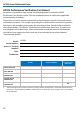
8. Record the displayed ‘Common Mode Signal at 70 Hz’ to two-digit resolution (0.xx
mV) in the Test Record.
9. Calculate the Common Mode Rejection Ratio (CMRR) at 70 Hz by dividing 8,000 mV
by the measured Common Mode Signal recorded in step C-8 (direct reciprocal of the