
Instructions


Operator’s Manual
29
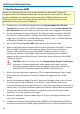
13. Move the leveled sine wave generator output cable from the Differential Drive 50
Ohm Termination connector of the AP033 Calibration Fixture to the Channel 2 input
of the oscilloscope.
14. Carefully move the AP033 probe head from the Differential Drive 50 Ohm
Termination connector of the AP033 Calibration Fixture to the Common Mode Drive
50 Ohm Termination connector. Make sure the probe is fully engaged in the fixture.
15. Set the oscilloscope to display Channel 2, change Channel 2 vertical scale to 0.5
Volt/div, Channel 2 input coupling to DC50Ω, and trigger source to Channel 2. If
necessary, adjust the trigger level for a stable display.
16. Set the sine wave generator output amplitude to exactly 2 V
p-p. (4 divisions on the
oscilloscope).
17. Remove the leveled sine wave generator output cable from the oscilloscope and
reconnect it to the Common Mode Drive 50 Ohm Termination input connector of
the AP033 Calibration Fixture.
18. Set the oscilloscope to display Math channel A (Averaged AP033 Output), and trigger
source to Channel 1.
19. Increase the Channel 1 vertical sensitivity as needed to view the signal.
20. Measure the peak to peak amplitude of the averaged waveform. This is the common
mode signal.
NOTE: The amplitude of the Common Mode signal should be relatively small. If the
output waveform appears to be a 1-Volt square wave, verify that the Common Mode
Drive 50 Ohm Termination connector of the AP033 Calibration Fixture is being used,
and not the Differential Drive 50 Ohm Termination connector.
21. Record the Common Mode signal amplitude to two-digit resolution (xx0 mV) in the
Test Record as ‘Common Mode Signal at 250 MHz’.
22. Calculate the Common Mode Gain by dividing the Common Mode signal recorded in
step B-21 (in mV) by 2,000 mV.
23. Record the result to two significant places as ‘Common Mode Gain at 250 MHz’ in the
Test Record. (Keep all of the leading zeros or use scientific notation.)
24. Calculate the Common Mode Rejection Ratio (CMRR) at 250 MHz by dividing the
Differential Mode Gain at 250 MHz recorded in step B-12 by the Common Mode Gain
recorded in step B-23.
25. Record the result as ‘Common Mode Rejection Ratio at 250 MHz’ in the Test Record
26. Verify that the CMRR at 250 MHz is greater than 5:1 (14 dB).
27. Disconnect the output and frequency reference cables from the leveled sine
wave generator.