
Instructions


AP033 Active Differential Probe
28
1. Disconnect the ProBus Extension cable from the AP033 and the oscilloscope.
Reconnect the AP033 directly to the Channel 1 input of the oscilloscope.
2. Carefully move the AP033 probe head from the Differential Drive No Termination
connector of the AP033 Calibration Fixture to the Differential Drive 50 Ohm
Termination connector. Make sure that the probe is fully engaged in the fixture.
3. Set the oscilloscope to display Channel 1. Set Coupling to DC 1 MΩ, and Global BWL
to Off. AP033 gain control to Manual, Probe Atten to /1 and Probe Gain to /1.
AutoZero the AP033. Set the oscilloscope trigger mode to AUTO.
4. If necessary, center the trace Vertical Offset.
5. Connect the output of the leveled sine wave generator to the Differential Drive 50
Ohm Termination connector of the AP033 Calibration Fixture. If using a model SG504
generator, insert a ÷2 50Ω BNC attenuator between the generator output and the
test fixture input.
6. Set the leveled sine wave generator frequency to 50 kHz, and the amplitude to
approximately 300 mV
p-p. When using a model SG504 generator, set the output to
0.6V pk-pk at the output which will correspond to 300 mV at the output of the ÷2
attenuator.
7. Set the oscilloscope vertical scale factor to 50 mV/div and the horizontal scale factor
to 10 μsec/div. Set the Trigger source to Channel 1. Adjust the trigger level for a
stable display. Turn on Math Channel A. Press MATH SETUP, then REDEFINE A. Set
the A Math type to Average, Avg Type to Continuous, with 1:15 weighting, of
Channel 1. Turn off the trace 1 display.
8. Adjust the output amplitude of the leveled sine wave generator for a display of
exactly 6 divisions (300 mV) peak to peak.
9. Change the leveled sine wave generator frequency to 250 MHz, taking care not to
change the output amplitude.
10. Change the oscilloscope horizontal scale to 1 ns/div. On the TIMEBASE setup, select
RIS Sampling. If necessary, turn the Channel 1 display back on and adjust the trigger
for a stable trace. Once a stable trace has been achieved, turn off the Channel 1 trace
to only display the averaged waveform.
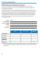
11. Measure the peak-to-peak output amplitude of the AP033. Record the reading to
two-digit resolution (xx0 mV) as ‘Probe Output Voltage at 250 MHz’ in the Test
Record.
12. Divide the measured output amplitude recorded in step B-11 by 300 mV. Record the
answer to two-digit resolution (0.xx) in the Test Record. This is the Differential Mode
Gain at 250 MHz.