
Instructions


Operator’s Manual
27
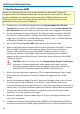
15. Record the answer to two significant places (±x.xx%) on line A-15 in the Test Record.
16. Verify that the X1 gain error is less than ±2%.
17. Change the probe Attenuation to /10 and the probe Gain to X10.
18. After the DMM reading has stabilized, record the measured output amplitude to 100
μV resolution in the Test Record.
19. Divide the measured output voltage recorded in step A-18 by the sine wave
generator output voltage (probe input voltage) from step A-7. Subtract 1.0 from the
ratio and multiply the result by 100 to get the error in percent.
20. Record the answer to two significant places (±x.xx%) on line A-20 in the Test Record.
21. Verify that the X10 gain error is less than ±2%.
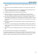
22. Divide the Sine Wave Generator output voltage recorded in step A-7 by 10. Record
the result as “Expected Probe Output Voltage” in the Test Record.
23. Return the probe Gain to X1. Leave the probe Attenuation set to /10.
24. After the DMM reading has stabilized, record the measured output amplitude to 10
μV resolution in the Test Record.
25. Calculate the error by dividing the measured output voltage recorded in step A-22.
Subtract 1.0 from this ratio and multiply by 100 to get the error in percent.
26. Record the calculated error to two decimal places (±x.xx%) as ÷10 Gain Error’ in the
Test Record.
27. Verify that the ÷10 gain error is less than ±2%.
28. Disconnect both BNC cables from the test setup.
B. Check High Frequency Common Mode Rejection Ratio (CMRR)
NOTE: Common Mode Rejection Ratio (CMRR) is defined as the Differential Mode Gain
divided by the Common Mode Gain (normalized inverse of the Common Mode response).
At higher frequencies where the bandwidth of the amplifier begins to attenuate the
differential mode signal, both the differential mode gain and common mode gain must be
measured to derive the CMRR.