
Instructions

Operator’s Manual
23
.
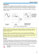
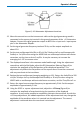
Figure 8, ÷10 Attenuator Adjustment Locations
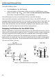
12. Move the connections on the interconnect cable so the signal generator ground is
connected to the square pin inserted in the ground connector of the ÷10 Attenuator
Adapter. Connect the signal generator output to BOTH the + input and – input square
pins in the Attenuator Adapter.
13. Set the signal generator frequency to about 50 Hz, and the output amplitude to
about 10 V.
14. Set the test oscilloscope Volts/Div to 20 mV (for Teledyne LeCroy oscilloscopes with
ProBus) or 2 mV/Div when using the ADPPS with an oscilloscope without scale factor
correction; set the time scale to 2 ms/Div. It may be necessary to increase the
averaging to 1:127 to remove noise.
15. The displayed waveform is the common mode feedthrough. Using the adjustment
screwdriver with the flat blade, adjust the DC Attenuation. Balance (Figure 8) to
minimize the amplitude of the flat portions of the displayed waveform. This
adjustment only affects the flat portions of the square wave. Do not be concerned
with any overshoot at the transitions.
16. Reduce the test oscilloscope Averaging weighting to 1:31. Return the Volts/Div to 200
mV (for Teledyne LeCroy oscilloscopes with ProBus) or 20 mV/Div when using the
ADPPS with an oscilloscope without scale factor correction, and the Time/Div to 5 us.
17. Return the signal source output frequency to approximately 5 kHz. Set the output
amplitude to approximately 1 Volt.
18. Using the 0.025 in. square adjustment tool, adjust the –LF Comp (Figure 8) to
minimize the amplitude of overshoot during the transition of the displayed
waveform. It may not be possible to completely eliminate the overshoot. As with the
+LF Comp adjustment, the added capacitance of the adjustment tool may change the
amplitude of the waveform when it is inserted into the adjustment. The correct
adjustment is achieved when the overshoot is minimized.