
Instructions

AP033 Active Differential Probe
22
Procedure
1. Attach the AP033 to the test oscilloscope. If the test oscilloscope is not equipped
with ProBus, use the ADPPS to provide power for the AP033.
2. Attach the ÷10 Attenuator Adapter to the AP033 probe tip.
3. Insert 0.025 in. (0.635 mm) square pins into the
+
,
-
, and input connectors of the
÷10 Attenuator Adapter.
4. Attach the interconnect cable to the output of the signal source.
5. Attach the Trigger Out signal from the signal source to the External Trigger Input of
the test oscilloscope. If the signal source does not have a separate Trigger Out signal,
use a BNC Tee connector in the output. Run one cable to the External Trigger Input of
the test oscilloscope. Connect the other to the probe inputs
6. Using the alligator clips on the end of the interconnect cable, connect the signal
source ground to the square pin on the ÷10 Attenuator Adapter’s “
-
“ input. Attach
the signal output to the square pin on the ÷10 Attenuator Adapter’s “
+
” input.
7. Turn on the test oscilloscope. On the AP033 dialog, change the Gain Control to
Manual and set the AP033 GAIN to X10. The EFFECTIVE GAIN indicator for
÷10 should be lit. (NOTE: If the X1 EFFECTIVE GAIN indicator is lit rather than the
÷10, make sure that the adapter installed on the probe tip is the ÷10 Attenuator,
and not the AC Coupler.)
8. Set the test oscilloscope Volts/Div to 200 mV (for Teledyne LeCroy oscilloscopes with
ProBus) or 20 mV/Div when using the ADPPS with an oscilloscope without scale
factor correction; 5 us/Div; AUTO trigger mode; Trigger source: External. Set the
Bandwidth Limiting to 20-30 MHz and Average the waveform 1:31 to reduce noise.
9. Turn on the signal source. Set the output frequency to approximately 5 kHz. Set the
output amplitude to approximately 1 Volt square wave.
10. Adjust the test oscilloscope trigger level for a stable trace. If necessary, use offset to
position the waveform to show the square corner of the test signal.
NOTE: Many of the signal generators used for compensation calibration only have
square corners on one of the two edges of the output waveform. (Rising or falling
edge, but not both.) Be sure to display the correct edge for this step.
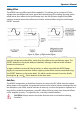
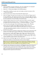
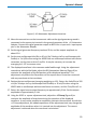
11. Using the square adjustment tool, adjust the +LF Comp (See Figure 8) to achieve the
best square corner and flat top of the displayed waveform. Note that the added
capacitance of the adjustment tool may change the compensation of the waveform
when it is inserted. The correct adjustment is achieved when the best corner is
displayed with the adjustment tool removed.