
Instructions

Operator’s Manual
21
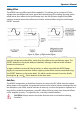
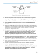
Matching Procedure for ÷10 Plugs
The ÷10 Plug-on attenuator provided as a standard accessory with the AP033 is calibrated
to match the specific probe it was shipped with. Individual probes will have small
variations in parasitic capacitance within the input circuits. To obtain maximum common
mode rejection performance, the attenuators are calibrated to match a specific probe
during the manufacturing process. In order to preserve the maximum Common Mode
Rejection, do not interchange external attenuators between probes.
The Plug-on AC coupling adapter is not matched to a specific probe and, therefore, does
not need to be matched. If the ÷10 Plug-on attenuators become accidentally mixed
between probes, you can use the procedure listed below to restore the compensation
match. This adjustment does not affect any of the parameters in the warranted
specifications. Therefore, the required test equipment does not need to be calibrated.
NOTE: The AP033 has different input capacitance. The 10 Plug-on attenuator supplied
with model AP033 cannot be properly adjusted for use with model AP033. Make sure that
the attenuator is marked “AP033” before attempting this procedure.
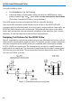
Equipment Required
Test Oscilloscope
The oscilloscope must support ProBus. For non-ProBus oscilloscopes, use the ADPPS
power supply.
Signal Source
Low frequency square wave: Frequency 50 Hz to 5 kHz, Amplitude 1 V to 10 V. The output
waveform must have a square corner and flat top with minimum overshoot suitable for
adjusting compensation. The generator should have trigger output, or use a BNC Tee
connector and separate BNC cable from the output to provide the trigger signal for the
test oscilloscope.
Interconnect Cable
This is for connecting the output of the signal source to the probe. A BNC cable and a pair
of small alligator clips or “lead grabber” adapter (Pomona #3788) may be used. 0.025 in.
(0.635 mm) Square Pins (3 required). The pins from the header supplied in the probe
accessory kit are suitable.
Tools
Flat bladed screwdriver, 0.040 in. (1 mm) wide
Adjustment Tool: 0.025 in. (0.635 mm) square head
NOTE: You can fabricate the Adjustment Tool by flattening the end of a 0.025 in. (0.635
mm) square pin with a file. Insert the pin into a short length of rigid plastic tubing to serve
as a handle.