
Instructions

Operator’s Manual
19
B. Incorrect Frequency Response
Possible causes are a defective probe or oscilloscope, poor connections, or poor
grounding.
1. Verify that the BW limiting of the oscilloscope is off.
2. Connect the probe to another oscilloscope. If the probe now measures properly, the
problem may be in the oscilloscope.
3. If the probe behaves as if it is AC-coupled at high frequency, check for an open input
connection. Poor frequency or transient response and AC gain errors may result
when one of the two input connections is open.
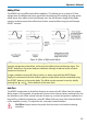
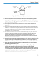
4. Excessive “ring” and other transient problems can result from excessive input lead
length. To test this, shorten the input leads to less than 1 cm. If the transient
response changes significantly, the lead parasitics are the cause.
C. DC Errors
Incorrect DC gain requires recalibration or factory repair. This can be determined by
completing the gain checks in the Performance Verification Procedure.
1. Extremely high source resistance will result in DC gain errors. Check the probe
accuracy with the oscilloscope calibrator signal.
2. Verify that the probe is not being overdriven into clipping for its current gain setting.
3. Excessive offset can result from large changes in ambient temperature. Remove the
input signal from the probe and repeat the AutoZero cycle. With the Offset set to
zero, did the trace return to the center of the graticule?
D. Poor Common Mode Rejection
Use the 1-kHz calibrator signal from the oscilloscope to check common mode rejection.
With both the + input and – input connected to the calibrator signal, a flat line at zero
volts should be seen on the graticule.
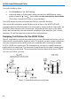
1. Check the probe with the plug-on attenuator installed and removed. If excessive
common mode signal appears only when the attenuator is present, the attenuator
may need to be rematched to the probe. Use the procedure listed in this section to
match the attenuator.
2. If the common mode signal appears when the probe is connected to the test circuit,
but not when it is attached to the calibrator, the problem may be caused by large
mismatches in the source impedance. Try connecting both inputs to one of the input
signals in the test circuit, then the other. If the common mode signal disappears, try
probing lower impedance points within the circuit.