
Instructions


AP033 Active Differential Probe
12
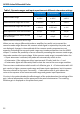
Table 1, Dynamic ranges and input capacitance at different attenuator settings
÷1 Attenuation ÷10 Attenuation ÷100 Attenuation
Common Mode Range
± 4.2 V ± 42 V ± 42 V
Differential Mode Range with x1 Gain*
± 400 mV ± 4 V ± 40 V
Differential Mode Range with x10 Gain*
± 40 mV ± 400 mV ± 4 V
Input Capacitance, each side to Ground
6.0 pF 3.0 pF 1.9 pF
Input Capacitance each side to Ground
with AC Coupler
7.3 pF 4.3 pF 3.2 pF
*Offset moves the center point of this range.
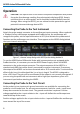
When you are using a differential probe or amplifier, be careful not to exceed the
common mode range. Because the common mode signal is rejected by the probe, and
not displayed, changes in the amplitude of the common mode component are not
apparent. Exceeding the common mode range may introduce distortion into the AP033
output. To reduce the possibility of errors caused by exceeding the common mode range,
the probe monitors the input voltage. If the common mode range is exceeded when the
÷1 input attenuator is selected, the probe will automatically switch to the
÷10 attenuator. If the voltage on either input exceeds 55 volts, both the ÷1 and
÷10 attenuator lights will alternately flash to alert the user to the over-range condition.
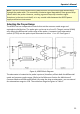
There are two combinations which result in x1 effective gain. A ÷10 attenuation with x10
gain results in higher common mode range and lower input capacitance, but it increases
the noise referred to the input. Conversely, ÷1 attenuation with x1 gain reduces the
noise at the expense of less common mode range and greater input capacitance.
Circuitry in the probe decodes the effective gain of the probe based on the settings of the
gain, internal attenuation and the presence of the external attenuator. The resulting
effective gain is displayed on the probe front panel.