
Instructions


Operator’s Manual
11
NOTE: The AP033 Active Differential Probe transmits the measured signal differentially
through the probe cable. This essentially eliminates signal degradation from ground loop
effects within the probe. However, creating a ground loop may introduce signal
distortions in the test circuit itself, or in any coaxial cable between the ADPPS power
supply and the test instrument.
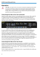
Selecting the Proper Range
The AP033 has two independent controls that set the common mode range and
equivalent volts/division. The probe gain can be set to x1 or x10. The gain control (GAIN)
only affects the differential mode range of the probe. A separate input attenuation
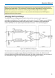
control (ATTEN) sets the probe input attenuator to either ÷1 or ÷10. See Figure 4.
Figure 4, AP033 Block Diagram
The attenuator is located at the probe input and, therefore, affects both the differential
mode and common mode ranges. (Refer to the Reference Section for definitions of
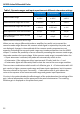
Common Mode and Differential Mode.) By using the plug-on attenuator, you can extend
the attenuation range to ÷100. The maximum ranges are given in Table 1.