
Instructions


AP033 Active Differential Probe
10
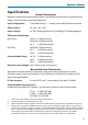
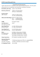
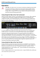
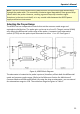
Probe Input Loading
Attaching any probe to a test circuit will add some loading. In most applications, the high
impedance of the AP033 Active Differential Probe inputs imparts an insignificant load to
the test circuit. However at very high frequencies, the capacitive reactance of the probe’s
input capacitance may load the circuit enough to affect measurement accuracy. The
equivalent model of the probe input circuits is shown below:
Figure 3, AP033 Equivalent Input Model
Grounding the Probe
The single lead along with one of the larger (0.8 mm) mini clips can be used to ground the
probe to the test circuit. Insert the pin end of the lead into the receptacle marked:
CAUTION: Do not use the attenuator encoding receptacle (unmarked socket
near the
– input) to ground the probe. Connection to the encoding receptacle
will not
provide adequate grounding and may result in an incorrect effective gain
indication.
In many cases it is not necessary to ground the probe to the circuit under test. However,
if the test circuit is isolated from earth ground, it is usually necessary to connect the
probe ground to a point in the circuit. Grounding test circuits that are referenced to earth
ground may improve the fidelity of high frequency components in the waveforms. The
potential for improvement with grounding will vary depending on the common mode
source impedance. However, connecting the probe ground to a circuit that is referenced
to earth ground can create a ground loop that may add noise to low amplitude signals.
The rejection of high frequency common mode signals is improved when the probe head
is ungrounded.
The best recommendation for connecting or not connecting the probe ground is to try
both configurations and select the one that performs the best.
M
M
M