
Instructions


Operator’s Manual
9
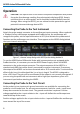
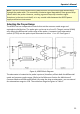
To maintain the high performance capability of the probe, user care in connecting the
probe to the test circuit. Increasing the parasitic capacitance or inductance in the input
paths may introduce a “ring,” or slow the rise time of fast signals. To minimize these
effects, use the shortest length possible when connecting the probe to the circuit under
test. Input leads that form a large loop area (even shielded coaxial cables) will pick up any
radiated magnetic field that passes through the loop, and may induce noise in the probe
inputs. Because this signal will appear as a differential mode signal, the probe’s common
mode rejection will not remove it. You can greatly reduce this effect by using short
interconnection leads, and twisting them together to minimize the loop area.
High common mode rejection requires precise matching of the relative gain or
attenuation in the + and – input signal paths. Mismatches in additional parasitic
capacitance, inductance, delay, and a source impedance difference between the + and –
signal paths will lower the common mode rejection ratio. Therefore, it is desirable to use
the same length and type of wire and connectors for both input connections. When
possible, try to connect the inputs to points in the circuit with approximately the same
source impedance.
If AC coupling is desired, install the AC coupling accessory on the probe tip before
connecting it to the test circuit. The low-frequency cutoff (–3 dB point) of the AC coupler
is approximately 1.6 Hz.
If the voltage in the test circuit requires more than ÷10 attentuation, add the external ÷10
attenuator to the probe tip. If using both the external attenuator and AC coupler, install
the attenuator on the probe tip first, then install the AC coupler on the attenuator input.
In addition to being compatible with the included lead set, the probe input connectors
will mate with standard 0.025 in. (0.635 mm) square pins in any rotational orientation. To
avoid damaging the input connectors, do not attempt to insert connectors or wire larger
than 0.036 in. (0.91 mm) in diameter. Avoid rotating square pins after they are inserted
into the input connectors.
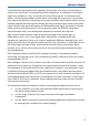
The included accessories simplify the task of connecting the probe to the test circuit:
• Use the small (0.5 mm) mini clips with the flexible lead set when connecting to
fine-pitch surface mount IC leads.
• Use the larger (0.8 mm) mini clips to connect to through-hole leaded
components.
• Use the offset round pins for hand-held probing applications. Reposition the pins
by rotating them to obtain the required spacing.