
Instructions


Operator’s Manual
5
Specifications
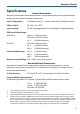
Nominal Characteristics
Nominal characteristics describe parameters and attributes that have are guaranteed by
design, but do not have associated tolerances.
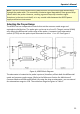
Input Configuration: True Differential (+ / – inputs); with shield Ground connector
Effective Gain:
1
X1, X10, ÷10, ÷100
2
Input coupling: DC (AC Coupling obtained by installing AC Coupling Adapter)
Differential Mode Range:
(10X Gain): ±40 mV (÷1 Attenuation)
±400 mV(÷10 Attenuation)
±4 V (÷100 Attenuation)
(1X Gain): ±400 mV(÷1 Attenuation)
±4 V (÷10 Attenuation)
±40 V (÷100 Attenuation)
Common Mode Range: ±4.2 V (÷1 Attenuation)
±42 V (÷10 Attenuation)
±42 V (÷100 Attenuation)
Maximum Input Voltage:
±42 V either input from ground
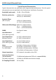
Warranted Electrical Characteristics
Warranted characteristics are parameters with guaranteed performance. Unless
otherwise noted, tests are provided in the Performance Verification Procedure for all
warranted specifications.
LF Gain Accuracy: 2% into 50 Ω load
3
, measured at 1 kHz with 0 V offset
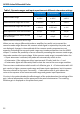
Common Mode Rejection Ratio:
4
(Probe head grounded, DC Coupled, ÷1 attenuation without external attenuator):
70 Hz ≥ 3160:1 (70 dB)
1 MHz ≥ 1000:1 (60 dB)
250 MHz ≥ 5:1(14 dB)
1. From combination of gain, internal and external attenuation.
2. Use external plug-on ÷10 attenuator for ÷100.
3. Output impedance 50 Ω, intended to drive 50 Ω. Add uncertainty of termination impedance to accuracy.
4. Teledyne LeCroy measures CMRR with a fixture that connects the probe tip ground to the signal source
ground. This method is necessary to obtain a reproducible CMRR measurement. Not grounding the probe
tip can actually improve CMRR by allowing some of the common mode signal to be impressed across the
entire length of the probe cable instead of from probe tip to probe ground, however, this CMRR
improvement depends on proximity to probe cable ground, and is therefore non-reproducible.