
Installation Manual
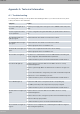
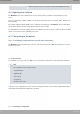
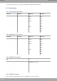
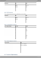
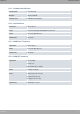
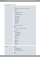
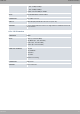
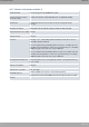
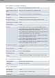
Table Of Contents
- Table of Contents
- I Related Documents
- 1 About This Guide
- 2 M8-Smart
- 3 Components and Power Supply
- 4 Compliance
- 4.1 Manufacturer Information
- 4.2 Risk identification
- 4.3 Safety Warnings
- 4.4 WEEE Information
- 4.5 REACH
- 4.6 Power Usage and Energy Efficiency
- 4.7 EC Declaration of Conformity (No Radio version)
- 4.8 EC Declaration of Conformity (Radio version)
- 4.9 CE Marking
- 4.10 National Restrictions
- 4.11 FCC Statements
- 4.12 Operating Frequency
- 4.13 Intended use of the equipment
- A Technical Information
- A.1 Troubleshooting
- A.2 Updating the software
- A.3 Connecting to the device
- A.4 Connectors
- A.5 Technical Specifications
- A.5.1 Hardware Architecture
- A.5.2 LAN Interface
- A.5.3 WAN Base-T Interface
- A.5.4 WAN SFP Interface
- A.5.5 Wireless WAN interface
- A.5.6 GPS interface
- A.5.7 Wireless LAN Interface (Radio 1)
- A.5.8 Wireless LAN Interface (Radio 2)
- A.5.9 Configuration Interface
- A.5.10 Power Supply
- A.5.11 Dimensions and weight
- A.5.12 Environmental Specifications
- B CE Radio Information
- C FCC Radio Information

For further information, please see manual: “Teldat Dm704-I Configuration and Monitoring”.
A.4 Connectors
A.4.1 LAN Connector (Switch)
RJ45 LAN RJ45 PIN FE Signals GE Signals
1
2
3
4
5
6
7
8
BI-DA+
BI-DA-
BI-DB+
--
--
BI-DB-
--
--
BI-DA+
BI-DA-
BI-DB+
BI-DC+
BI-DC-
BI-DB-
BI-DD+
BI-DD-
A.4.2 WAN Base-T Connector
RJ45 WAN RJ45 PIN FE Signals GE Signals
1
2
3
4
5
6
7
8
BI-DA+
BI-DA-
BI-DB+
--
--
BI-DB-
--
--
BI-DA+
BI-DA-
BI-DB+
BI-DC+
BI-DC-
BI-DB-
BI-DD+
BI-DD-
A.4.3 WAN SFP Connector
SFP
Standard SFP connector
A.4.4 WWAN Connector
Devices equipped with this interface have up to four SMA female connectors installed.
Teldat S.A.
Technical Information
M8-Smart 29