
Installation Manual

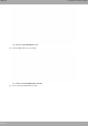
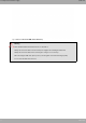
Table Of Contents
- Table of Contents
- I Related Documents
- 1 About This Guide
- 2 M8-Smart
- 3 Components and Power Supply
- 4 Compliance
- 4.1 Manufacturer Information
- 4.2 Risk identification
- 4.3 Safety Warnings
- 4.4 WEEE Information
- 4.5 REACH
- 4.6 Power Usage and Energy Efficiency
- 4.7 EC Declaration of Conformity (No Radio version)
- 4.8 EC Declaration of Conformity (Radio version)
- 4.9 CE Marking
- 4.10 National Restrictions
- 4.11 FCC Statements
- 4.12 Operating Frequency
- 4.13 Intended use of the equipment
- A Technical Information
- A.1 Troubleshooting
- A.2 Updating the software
- A.3 Connecting to the device
- A.4 Connectors
- A.5 Technical Specifications
- A.5.1 Hardware Architecture
- A.5.2 LAN Interface
- A.5.3 WAN Base-T Interface
- A.5.4 WAN SFP Interface
- A.5.5 Wireless WAN interface
- A.5.6 GPS interface
- A.5.7 Wireless LAN Interface (Radio 1)
- A.5.8 Wireless LAN Interface (Radio 2)
- A.5.9 Configuration Interface
- A.5.10 Power Supply
- A.5.11 Dimensions and weight
- A.5.12 Environmental Specifications
- B CE Radio Information
- C FCC Radio Information

Fig. 27: WWAN Main and Aux 1 antennas
Fig. 28: WWAN Aux 2 and Aux 3 antennas (future use)
When the Main and Aux 1 antennas are not directly connected to the router but installed through extension cords,
the minimum distance between the two must be 7 cm. The maximum recommended distance between them is 25
cm.
To achieve optimum performance, the radio frequency accessories installed (antennas and cables) should be those
recommended by Teldat.
Teldat offers a range of suitable accessories (90º mount antennas, antennas for outdoor installation, antennas for
ceiling installation, extension cables, etc.) for different locations.
3.7.3.1 Placing the Antenna
The orientation of the antenna and its location with respect to other wireless devices and radiation sources (such as
communication devices, personal computers, etc.) can influence device performance.
Antennas transmit and receive radio signals. Environmental factors (such as the distance between the device and
the base station), physical obstacles and other RF interferences can impact their performance.
For optimum coverage, follow these steps:
• Whenever possible, place the antenna where there are no physical obstacles. Obstacles between the antenna and
the base station degrade the wireless signal. Place the antenna above ground level facing the nearest base sta-
tion.
• Density of materials also affects antennas. Place them away from any type of wall, metal screens, mirrors, etc.
• Do not place the antenna near columns, which may throw shadows and reduce the coverage area.
• Keep the antenna away from metal pipes (such as canals, air-conditioning, etc.).
• Please bear in mind that other wireless devices such as telephones, microwaves, etc., can temporarily interfere
with the quality of the radio signal.
• We do not recommend installing antennas near, or between, racks containing communication devices, computers,
etc. Use an extension cable and place the device outside.
The following recommendations are applicable to all wireless devices:
• Do not touch or move the antenna while the device is transmitting or receiving.
• When the antenna is transmitting, do not touch any equipment that contains devices that radiate very close to, or
touching, any exposed part of the body (particularly face and eyes).
3 Components and Power Supply Teldat S.A.
16 M8-Smart