
Installation Manual
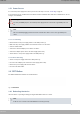
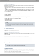
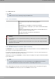
Table Of Contents
- Table of Contents
- I Related Documents
- 1 About This Guide
- 2 M8-Smart
- 3 Components and Power Supply
- 4 Compliance
- 4.1 Manufacturer Information
- 4.2 Risk identification
- 4.3 Safety Warnings
- 4.4 WEEE Information
- 4.5 REACH
- 4.6 Power Usage and Energy Efficiency
- 4.7 EC Declaration of Conformity (No Radio version)
- 4.8 EC Declaration of Conformity (Radio version)
- 4.9 CE Marking
- 4.10 National Restrictions
- 4.11 FCC Statements
- 4.12 Operating Frequency
- 4.13 Intended use of the equipment
- A Technical Information
- A.1 Troubleshooting
- A.2 Updating the software
- A.3 Connecting to the device
- A.4 Connectors
- A.5 Technical Specifications
- A.5.1 Hardware Architecture
- A.5.2 LAN Interface
- A.5.3 WAN Base-T Interface
- A.5.4 WAN SFP Interface
- A.5.5 Wireless WAN interface
- A.5.6 GPS interface
- A.5.7 Wireless LAN Interface (Radio 1)
- A.5.8 Wireless LAN Interface (Radio 2)
- A.5.9 Configuration Interface
- A.5.10 Power Supply
- A.5.11 Dimensions and weight
- A.5.12 Environmental Specifications
- B CE Radio Information
- C FCC Radio Information

3.6.2 Default Configuration
The RST button allows you to boot the device with its default configuration (including the embedded Access Point, if
present) through the following steps:
• With the device switched off, press and hold the RST button down while you turn on the router using the ON/OFF
switch (1).
• The PWR LED (green) will light up and LED 'S' will begin to blink (amber). It will carry on blinking for 10 seconds.
• To boot the device with the default configuration, release the RST button while LED 'S' is still blinking (i.e. before
the 10-second period expires).
The router's default configuration establishes the following access IP and mask address:
• IP address: 192.168.1.1
• IP mask: 255.255.255.0
If available, the embedded access point's default configuration establishes the following parameters:
• IP address: DHCP client with no. 192.168.0.252/24 as default
• Credentials: admin / admin
• Only GUI access enabled
Note
Some devices leave the factory with customized settings. This personalization means your router's de-
fault configuration (and that of the embedded access point, where applicable) may be different from the
one shown above.
3.7 Data connections
The M8-Smart router has the following data connections.
3.7.1 4-port Ethernet switch Connections
The M8-Smart router incorporates a 4-port 10/100/1000 Base-T switch with automatic MDI/MDIX to connect to a loc-
al area network (LAN).
Please pay careful attention to the labeling to avoid mistaking this switch for other types of ports:
Fig. 24: LAN switch ports
Note
Only the LAN 1 connector is available during booting and in BIOS mode.
3.7.2 WAN Connections
The M8-Smart has 4 Ethernet interfaces for WAN connection. These ports have 2 connectors - SFP for an optical
link and RJ45 for a 10/100/1000 Base-T link - but they cannot work simultaneously. These interfaces are totally inde-
pendent from the switch and are handled as every other interface.
Please pay careful attention to the labeling to avoid mistaking these ports for other types of ports:
3 Components and Power Supply Teldat S.A.
14 M8-Smart