
Installation Manual
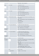
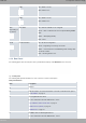
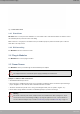
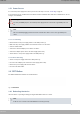
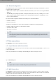
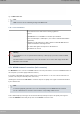
Table Of Contents
- Table of Contents
- I Related Documents
- 1 About This Guide
- 2 M8-Smart
- 3 Components and Power Supply
- 4 Compliance
- 4.1 Manufacturer Information
- 4.2 Risk identification
- 4.3 Safety Warnings
- 4.4 WEEE Information
- 4.5 REACH
- 4.6 Power Usage and Energy Efficiency
- 4.7 EC Declaration of Conformity (No Radio version)
- 4.8 EC Declaration of Conformity (Radio version)
- 4.9 CE Marking
- 4.10 National Restrictions
- 4.11 FCC Statements
- 4.12 Operating Frequency
- 4.13 Intended use of the equipment
- A Technical Information
- A.1 Troubleshooting
- A.2 Updating the software
- A.3 Connecting to the device
- A.4 Connectors
- A.5 Technical Specifications
- A.5.1 Hardware Architecture
- A.5.2 LAN Interface
- A.5.3 WAN Base-T Interface
- A.5.4 WAN SFP Interface
- A.5.5 Wireless WAN interface
- A.5.6 GPS interface
- A.5.7 Wireless LAN Interface (Radio 1)
- A.5.8 Wireless LAN Interface (Radio 2)
- A.5.9 Configuration Interface
- A.5.10 Power Supply
- A.5.11 Dimensions and weight
- A.5.12 Environmental Specifications
- B CE Radio Information
- C FCC Radio Information

Fig. 18: WAN LEDs
WAN LED indicators
LED Description
Yellow Connected to 10 M:
- Steady: Not transferring data.
- Blinking: Transferring data.
Yellow + Green Connected to 100 M:
- Steady: Not transferring data.
- Blinking: Transferring data.
Green Connected to 1000 M:
- Steady: Not transferring data.
- Blinking: Transferring data.
None Interface is either unavailable, not installed or not registered.
3.1.3 Side Panels
Two antenna connectors are located on the side panels.
Fig. 19: Left and right side panels
The connectors are as follows:
Side panel connectors
Item Description
A Aux 2 and Aux 3 connectors. Reserved for future use.
3 Components and Power Supply Teldat S.A.
10 M8-Smart